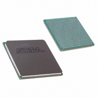
EP20K400EFC672-2X Altera, EP20K400EFC672-2X Datasheet - Page 113

EP20K400EFC672-2X
Manufacturer Part Number
EP20K400EFC672-2X
Description
IC APEX 20KE FPGA 400K 672-FBGA
Manufacturer
Altera
Series
APEX-20K®r
Datasheet
1.EP20K30ETC144-3.pdf
(117 pages)
Specifications of EP20K400EFC672-2X
Number Of Logic Elements/cells
16640
Number Of Labs/clbs
1664
Total Ram Bits
212992
Number Of I /o
488
Number Of Gates
1052000
Voltage - Supply
1.71 V ~ 1.89 V
Mounting Type
Surface Mount
Operating Temperature
0°C ~ 85°C
Package / Case
672-FBGA
Family Name
APEX 20K
Number Of Usable Gates
400000
Number Of Logic Blocks/elements
16640
# Registers
104
# I/os (max)
488
Frequency (max)
223MHz
Process Technology
SRAM
Operating Supply Voltage (typ)
1.8V
Logic Cells
16640
Ram Bits
212992
Device System Gates
1052000
Operating Supply Voltage (min)
1.71V
Operating Supply Voltage (max)
1.89V
Operating Temp Range
0C to 85C
Operating Temperature Classification
Commercial
Mounting
Surface Mount
Pin Count
672
Package Type
FC-FBGA
Lead Free Status / RoHS Status
Contains lead / RoHS non-compliant
Other names
544-2095
Available stocks
Company
Part Number
Manufacturer
Quantity
Price
Company:
Part Number:
EP20K400EFC672-2X
Manufacturer:
ALTERA
Quantity:
586
Part Number:
EP20K400EFC672-2X
Manufacturer:
ALTERA/阿尔特拉
Quantity:
20 000
Company:
Part Number:
EP20K400EFC672-2XB
Manufacturer:
ALTERA
Quantity:
3 000
Altera Corporation
Power
Consumption
Configuration &
Operation
LVCMOS
LVTTL
2.5 V
1.8 V
PCI
GTL+
SSTL-3 Class I
SSTL-3 Class II
SSTL-2 Class I
SSTL-2 Class II
LVDS
CTT
AGP
Table 110. Selectable I/O Standard Output Delays
Symbol
Min
-1 Speed Grade
To estimate device power consumption, use the interactive power
calculator on the Altera web site at http://www.altera.com.
The APEX 20K architecture supports several configuration schemes. This
section summarizes the device operating modes and available device
configuration schemes.
Operating Modes
The APEX architecture uses SRAM configuration elements that require
configuration data to be loaded each time the circuit powers up. The
process of physically loading the SRAM data into the device is called
configuration. During initialization, which occurs immediately after
configuration, the device resets registers, enables I/O pins, and begins to
operate as a logic device. The I/O pins are tri-stated during power-up,
and before and during configuration. Together, the configuration and
initialization processes are called command mode; normal device operation
is called user mode.
Before and during device configuration, all I/O pins are pulled to V
by a built-in weak pull-up resistor.
–0.03
–0.48
Max
0.00
0.00
0.00
2.49
0.75
1.39
1.11
1.35
1.00
0.00
0.00
APEX 20K Programmable Logic Device Family Data Sheet
Min
-2 Speed Grade
–0.48
Max
0.00
0.00
0.09
2.98
0.17
0.75
1.51
1.23
1.48
1.12
0.00
0.00
Min
-3 Speed Grade
–0.48
Max
0.00
0.00
0.10
3.03
0.16
0.76
1.50
1.23
1.47
1.12
0.00
0.00
Unit
Min
ns
ns
ns
ns
ns
ns
ns
ns
ns
ns
ns
ns
ns
CCIO
113


