MPC8248VRPIEA Freescale Semiconductor, MPC8248VRPIEA Datasheet - Page 34
MPC8248VRPIEA
Manufacturer Part Number
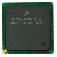
MPC8248VRPIEA
Description
IC MPU POWERQUICC II 516-PBGA
Manufacturer
Freescale Semiconductor
Series
PowerQUICC IIr
Datasheet
1.MPC8248VRMIBA.pdf
(60 pages)
Specifications of MPC8248VRPIEA
Processor Type
MPC82xx PowerQUICC II 32-bit
Speed
300MHz
Voltage
1.5V
Mounting Type
Surface Mount
Package / Case
516-PBGA
Processor Series
MPC8xxx
Core
603e
Data Bus Width
32 bit
Maximum Clock Frequency
300 MHz
Operating Supply Voltage
1.4 V to 1.6 V
Maximum Operating Temperature
+ 105 C
Mounting Style
SMD/SMT
Data Ram Size
4 KB
Minimum Operating Temperature
0 C
Number Of Programmable I/os
14
Program Memory Size
16 KB
Program Memory Type
EEPROM
Core Size
32 Bit
Cpu Speed
300MHz
Embedded Interface Type
I2C, JTAG, SPI, UART
Digital Ic Case Style
BGA
No. Of Pins
516
Rohs Compliant
Yes
For Use With
CWH-PPC-8248N-VE - KIT EVAL SYSTEM QUICCSTART 8248
Lead Free Status / RoHS Status
Lead free / RoHS Compliant
Features
-
Lead Free Status / Rohs Status
Lead free / RoHS Compliant
Available stocks
Company
Part Number
Manufacturer
Quantity
Price
Company:

Part Number:
MPC8248VRPIEA
Manufacturer:
Freescale Semiconductor
Quantity:
135
Company:
Part Number:
MPC8248VRPIEA
Manufacturer:
Freescale Semiconductor
Quantity:
10 000


Clock Configuration Modes
34
1
2
3
4
5
6
MODCK[1-3]
MODCK_H-
table entry guarantees only the required minimum CPU operating frequency. The “high” values are for the purpose
of illustration only. Users must select a mode and input bus frequency so that the resulting configuration does not
exceed the frequency rating of the user’s device. The minimum CPU frequency is 150 MHz for commercial
temperature devices and 175 MHz for extended temperature devices. The minimum CPM frequency is 120 MHz.
MODCK[1-3] = three hardware configuration pins.
PCIDF as follows:
PCIDF = 3 > CPM_CLK/PCI_CLK = 4
PCIDF = 5 > CPM_CLK/PCI_CLK = 6
PCIDF = 7 > CPM_CLK/PCI_CLK = 8
PCIDF = 9 > CPM_CLK/PCI_CLK = 5
PCIDF = B > CPM_CLK/PCI_CLK = 6
The “low” values are the minimum allowable frequencies for a given clock mode. The minimum bus frequency in a
PCI_MODCK determines the PCI clock frequency range. Refer to
MODCK_H = hard reset configuration word [28–31] (refer to Section 5.4 in the MPC8260 User’s Manual ).
CPM multiplication factor = CPM clock/bus clock
CPU multiplication factor = Core PLL multiplication factor
CPM_CLK/PCI_CLK ratio. When PCI_MODCK = 1, the ratio of CPM_CLK/PCI_CLK should be calculated from
1110_001
1110_010
1110_011
1110_100
1100_000
1100_001
1100_010
Mode
Table 17. Clock Configurations for PCI Host Mode (PCI_MODCK=1)
3
Low
50.0 100.0
50.0 100.0
50.0 100.0
50.0 100.0
Bus Clock
(MHz)
MPC8272 PowerQUICC II™ Family Hardware Specifications, Rev. 2
High
Multiplication
Factor
CPM
3
3
3
3
4
150.0 300.0
150.0 300.0
150.0 300.0
150.0 300.0
CPM Clock
Low
(MHz)
High
Reserved
Reserved
Reserved
Multiplication
Factor
CPU
4.5
5.5
Table 16
4
5
5
for higher range configurations.
200.0 400.0
225.0 450.0
250.0 500.0
275.0 550.0
CPU Clock
Low
(MHz)
High
1, 2
Division
Factor
(continued)
PCI
Freescale Semiconductor
6
6
6
6
6
Low
25.0
25.0
25.0
25.0
PCI Clock
(MHz)
High
50.0
50.0
50.0
50.0
Related parts for MPC8248VRPIEA
Image
Part Number
Description
Manufacturer
Datasheet
Request
R

Part Number:
Description:
Mpc8248 Powerquicc Ii Integrated Communications Processor
Manufacturer:
Freescale Semiconductor, Inc
Datasheet:
Part Number:
Description:
Manufacturer:
Freescale Semiconductor, Inc
Datasheet:
Part Number:
Description:
Manufacturer:
Freescale Semiconductor, Inc
Datasheet:
Part Number:
Description:
Manufacturer:
Freescale Semiconductor, Inc
Datasheet:
Part Number:
Description:
Manufacturer:
Freescale Semiconductor, Inc
Datasheet:
Part Number:
Description:
Manufacturer:
Freescale Semiconductor, Inc
Datasheet:
Part Number:
Description:
Manufacturer:
Freescale Semiconductor, Inc
Datasheet:
Part Number:
Description:
Manufacturer:
Freescale Semiconductor, Inc
Datasheet:
Part Number:
Description:
Manufacturer:
Freescale Semiconductor, Inc
Datasheet:
Part Number:
Description:
Manufacturer:
Freescale Semiconductor, Inc
Datasheet:
Part Number:
Description:
Manufacturer:
Freescale Semiconductor, Inc
Datasheet:
Part Number:
Description:
Manufacturer:
Freescale Semiconductor, Inc
Datasheet:
Part Number:
Description:
Manufacturer:
Freescale Semiconductor, Inc
Datasheet:
Part Number:
Description:
Manufacturer:
Freescale Semiconductor, Inc
Datasheet:
Part Number:
Description:
Manufacturer:
Freescale Semiconductor, Inc
Datasheet: