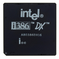
A80386DX16 Intel, A80386DX16 Datasheet - Page 70

A80386DX16
Manufacturer Part Number
A80386DX16
Description
IC MPU 32-BIT 5V 16MHZ 132-PGA
Manufacturer
Intel
Datasheet
1.A80386DX16.pdf
(139 pages)
Specifications of A80386DX16
Processor Type
386DX
Features
32-bit
Speed
16MHz
Voltage
5V
Mounting Type
Surface Mount
Package / Case
132-PGA
Family Name
Intel386 DX
Device Core Size
32b
Frequency (max)
16MHz
Supply Voltage 1 (typ)
5V
Operating Supply Voltage (max)
5.25V
Operating Supply Voltage (min)
4.75V
Operating Temp Range
0C to 85C
Operating Temperature Classification
Commercial
Mounting
Through Hole
Pin Count
132
Package Type
PGA
Lead Free Status / RoHS Status
Contains lead / RoHS non-compliant
Other names
807050
Available stocks
Company
Part Number
Manufacturer
Quantity
Price
Intel386
Effect of asserting BS16
read cycles
Effect of asserting BS16
write cycles
Effect of asserting BS16
half’’ read cycles
70
Asserting BS16
causes the Intel386 DX to read data on the lower
16 bits of the data bus and ignore data on the
upper 16 bits of the data bus Data that would
have been read from D16– D31 (as indicated by
BE2
D15 respectively
Asserting BS16
does not affect the Intel386 DX When only BE2
and or BE3
the Intel386 DX always duplicates data signals
D16–D31 onto D0 – D15 (see Table 5-1) There-
fore no further Intel386 DX action is required to
perform these writes on 32-bit or 16-bit buses
Asserting BS16
reads causes the processor to perform two 16-bit
read cycles for complete physical operand trans-
fer Bytes 0 and 1 (as indicated by BE0
BE1 ) are read on the first cycle using D0 – D15
Bytes 2 and 3 (as indicated by BE2
are read during the second cycle again using
D0–D15 D16– D31 are ignored during both 16-bit
cycles BE0
ing the second 16-bit cycle (See Figure 5-14 cy-
cles 2 and 2a)
and BE3 ) will instead be read from D0 –
TM
DX MICROPROCESSOR
and BE1
are asserted during a write cycle
during ‘‘upper half only’’ reads
during ‘‘upper half only’’ writes
during ‘‘upper and lower half’’
Figure 5-6 Intel386
during ‘‘upper and lower
during ‘‘upper half only’’
during ‘‘upper half only’’
are always negated dur-
Figure 5-5 Intel386
and BE3 )
TM
and
DX with 32-Bit and 16-Bit Memory
TM
DX with 32-Bit Memory
Effect of asserting BS16
half’’ write cycles
5 3 5 Interfacing with 32- and 16-Bit
In 32-bit-wide physical memories such as Figure 5-5
each physical Dword begins at a byte address that is
a multiple of 4 A2 – A31 are directly used as a Dword
select and BE0 – BE3
negated for all bus cycles involving the 32-bit array
When 16-bit-wide physical arrays are included in the
system as in Figure 5-6 each 16-bit physical word
begins at a address that is a multiple of 2 Note the
address is decoded to assert BS16
bus cycles involving the 16-bit array (If desiring to
Asserting BS16
writes causes the Intel386 DX to perform two
16-bit write cycles for complete physical operand
transfer All bytes are available the first write cycle
allowing external hardware to receive Bytes 0 and
1 (as indicated by BE0
D15 On the second cycle the Intel386 DX dupli-
cates Bytes 2 and 3 on D0 – D15 and Bytes 2 and
3 (as indicated by BE2
using D0 – D15 BE0
ated during the second 16-bit cycle BS16
be asserted during the second 16-bit cycle See
Figure 5-14 cycles 1 and 1a
Memories
during ‘‘upper and lower half’’
and BE1
as byte selects BS16
231630 –6
during ‘‘upper and lower
and BE3 ) are written
and BE1 ) using D0 –
231630 –7
are always neg-
only during
must
is


