MPC8347CVRAGDB Freescale Semiconductor, MPC8347CVRAGDB Datasheet - Page 25
MPC8347CVRAGDB
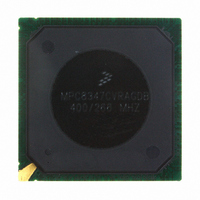
Manufacturer Part Number
MPC8347CVRAGDB
Description
IC MPU POWERQUICC II 620-PBGA
Manufacturer
Freescale Semiconductor
Series
PowerQUICC II PROr
Specifications of MPC8347CVRAGDB
Processor Type
MPC83xx PowerQUICC II Pro 32-Bit
Speed
400MHz
Voltage
1.2V
Mounting Type
Surface Mount
Package / Case
620-PBGA
Core Size
32 Bit
Program Memory Size
64KB
Cpu Speed
400MHz
Embedded Interface Type
I2C, SPI, USB, UART
Digital Ic Case Style
BGA
No. Of Pins
672
Rohs Compliant
Yes
Lead Free Status / RoHS Status
Lead free / RoHS Compliant
Features
-
Available stocks
Company
Part Number
Manufacturer
Quantity
Price
Company:

Part Number:
MPC8347CVRAGDB
Manufacturer:
FREESCA
Quantity:
13
Company:
Part Number:
MPC8347CVRAGDB
Manufacturer:
Freescale Semiconductor
Quantity:
10 000


8.2.1.2
Table 26
Figure 9
Freescale Semiconductor
At recommended operating conditions with LV
RX_CLK clock period
RX_CLK duty cycle
RXD[7:0], RX_DV, RX_ER setup time to RX_CLK
RXD[7:0], RX_DV, RX_ER hold time to RX_CLK
RX_CLK clock rise (20%–80%)
RX_CLK clock fall time (80%–20%)
Note:
1. The symbols for timing specifications follow the pattern of t
G
and t
(GR) with respect to the time data input signals (D) reaching the valid state (V) relative to the t
to the high state (H) or setup time. Also, t
signals (D) went invalid (X) relative to the t
reference symbol is based on three letters representing the clock of a particular function. For example, the subscript of t
represents the GMII (G) receive (RX) clock. For rise and fall times, the latter convention is used with the appropriate letter:
R (rise) or F (fall).
(first two letters of functional block)(reference)(state)(signal)(state)
shows the GMII receive AC timing diagram.
provides the GMII receive AC timing specifications.
MPC8347EA PowerQUICC II Pro Integrated Host Processor Hardware Specifications, Rev. 11
GMII Receive AC Timing Specifications
RXD[7:0]
RX_CLK
Parameter/Condition
RX_DV
RX_ER
Table 26. GMII Receive AC Timing Specifications
Figure 9. GMII Receive AC Timing Diagram
t
t
GRXH
GRDVKH
DD
/OV
GRDXKL
GRX
t
DD
GRX
clock reference (K) going to the low (L) state or hold time. In general, the clock
of 3.3 V ± 10%.
symbolizes GMII receive timing (GR) with respect to the time data input
for outputs. For example, t
(first two letters of functional block)(signal)(state)(reference)(state)
t
t
GRXF
GRXH
Symbol
t
t
GRDVKH
GRDXKH
t
t
t
GRXR
GRXF
GRX
t
GRDXKH
/t
GRX
1
t
GRXR
Ethernet: Three-Speed Ethernet, MII Management
Min
2.0
0.5
40
—
—
—
GRDVKH
symbolizes GMII receive timing
Typ
8.0
—
—
—
—
—
RX
clock reference (K) going
Max
1.0
1.0
60
—
—
—
for inputs
Unit
ns
ns
ns
ns
ns
%
GRX
25
Related parts for MPC8347CVRAGDB
Image
Part Number
Description
Manufacturer
Datasheet
Request
R

Part Number:
Description:
Manufacturer:
Freescale Semiconductor, Inc
Datasheet:
Part Number:
Description:
Manufacturer:
Freescale Semiconductor, Inc
Datasheet:
Part Number:
Description:
Manufacturer:
Freescale Semiconductor, Inc
Datasheet:
Part Number:
Description:
Manufacturer:
Freescale Semiconductor, Inc
Datasheet:
Part Number:
Description:
Manufacturer:
Freescale Semiconductor, Inc
Datasheet:
Part Number:
Description:
Manufacturer:
Freescale Semiconductor, Inc
Datasheet:
Part Number:
Description:
Manufacturer:
Freescale Semiconductor, Inc
Datasheet:
Part Number:
Description:
Manufacturer:
Freescale Semiconductor, Inc
Datasheet:
Part Number:
Description:
Manufacturer:
Freescale Semiconductor, Inc
Datasheet:
Part Number:
Description:
Manufacturer:
Freescale Semiconductor, Inc
Datasheet:
Part Number:
Description:
Manufacturer:
Freescale Semiconductor, Inc
Datasheet:
Part Number:
Description:
Manufacturer:
Freescale Semiconductor, Inc
Datasheet:
Part Number:
Description:
Manufacturer:
Freescale Semiconductor, Inc
Datasheet:
Part Number:
Description:
Manufacturer:
Freescale Semiconductor, Inc
Datasheet:
Part Number:
Description:
Manufacturer:
Freescale Semiconductor, Inc
Datasheet: