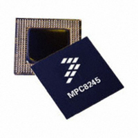
MPC8245LVV266D Freescale Semiconductor, MPC8245LVV266D Datasheet - Page 57

MPC8245LVV266D
Manufacturer Part Number
MPC8245LVV266D
Description
IC MPU 32BIT 266MHZ PPC 352-TBGA
Manufacturer
Freescale Semiconductor
Series
PowerQUICC IIr
Datasheet
1.MPC8245LZU266D.pdf
(68 pages)
Specifications of MPC8245LVV266D
Processor Type
MPC82xx PowerQUICC II 32-bit
Speed
266MHz
Voltage
1.8V
Mounting Type
Surface Mount
Package / Case
352-TBGA
Core Size
32 Bit
Program Memory Size
32KB
Cpu Speed
266MHz
Embedded Interface Type
I2C, UART
Digital Ic Case Style
TBGA
No. Of Pins
352
Supply Voltage Range
1.7V To 2.1V
Rohs Compliant
Yes
Lead Free Status / RoHS Status
Lead free / RoHS Compliant
Features
-
Available stocks
Company
Part Number
Manufacturer
Quantity
Price
Company:
Part Number:
MPC8245LVV266D
Manufacturer:
Freescal
Quantity:
672
Company:
Part Number:
MPC8245LVV266D
Manufacturer:
Freescale Semiconductor
Quantity:
10 000
Part Number:
MPC8245LVV266D
Manufacturer:
FREESCALE
Quantity:
20 000
Freescale Semiconductor
Revision
5
4
3
Date
—
—
—
Section 4.1.2 — Added note 6 and related label for latching of the PLL_CFG signals.
Section 4.1.3 — Updated specifications for the input high and input low voltages of PCI_SYNC_IN.
Section 4.3 — Table 7, updated specifications for the voltage range of V
frequencies.
Section 4.3.1 — Table 8: Corrected typo for first number 1a to 1; Updated characteristics for the DLL
lock range for the default and remaining three DLL locking modes; Reworded note description for note
6. Replaced contents of Table 9 with bit descriptions for the four DLL locking modes. In Figures 7
through 10, updated the DLL locking mode graphs.
Section 4.3.2 — Table 10: Changed the name of references for timing parameters from
SDRAM_SYNC_IN to sys_logic_clk to be consistent with Figure 11. Followed the same change for
note 2.
Section 4.3.3— Table 11: Changed the name of references for timing parameters from
SDRAM_SYNC_IN to sys_logic_clk to be consistent with Figure 11. Followed the same change for
note 2.
Section 5.3 — Table 17: Removed extra listing of DRDY in Test/Configuration signal list and updated
relevant notes for signal in Memory Interface signal listing. Updated note #20. Added note 26 for the
signals of the UART interface.
Section 7.6 — Added reference to AN2128 application note that highlights the differences between the
MPC8240 and the MPC8245.
Section 7.7 — Added relevant notes to this section and updated Figure 29.
Section 1.4.1.2—Updated notes for GV
Section 1.5.1—Updated solder ball information to include lead-free (V V) balls.
Section 1.5.3—Updated Note 25 for QACK/DA0 signal. Added a sentence to Note 3.
Section 1.6 —Incorporated Note 19 into Note 12 and modified Tables 18 and 19 accordingly.
Section 1.9—Updated part marking nomenclature where appropriate to include the lead-free offering.
Replaced reference to PNS document MPC8245RZUPNS with MPC8245ARZUPNS.
Section 1.4.1.2—Figure 2: Updated Note 2 and removed ‘voltage regulator delay’ label since Section
1.7.2 is being deleted this revision. Added Figures 4 and 5 to show voltage overshoot and undershoot
of the PCI interface on the MPC8245.
Section 1.4.1.3—Table 3: Updated the maximum input capacitance from 7 to 16 pF based on
characterization data.
Section 1.4.3.1—Updated PCI_SYNC_IN jitter specifications to 200 ps.
Section 1.4.3.3—Table 11, item 12b: added the word ‘address’ to help clarify which signals the spec
applies to. Figure 15: edited timing for items 12a0 and 12a2 to correspond with Table 11.
Section 1.5.3—Updated notes for the QACK/DA0 signal because this signal has been found to have
no internal pull resistor.
Section 1.6—Corrected note numbers for reference numbers 3,10,1B, and 1C of the PLL tables.
Updated PLL specifications for modes 7 and 1E.
Section 1.7.2—Removed this section since the information already exists in Section 1.4.1.5.
Section 1.7.4—Added the words ‘the clamping voltage’ to describe LV
Changed the QACK/DA0 signal from the list of signals having an internal pull-up resistor to the list of
signals needing a weak pull-up resistor to OV
Section 1.9.1—Tables 21 thru 23: Added processor version register value.
MPC8245 Integrated Processor Hardware Specifications, Rev. 10
Table 19. Revision History Table (continued)
Substantive Change(s)
DD
, AV
DD
DD
.
, AV
DD2
.
DD
DD
in the sixth paragraph.
for specific CPU
Document Revision History
57


