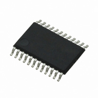
CS4270-DZZ Cirrus Logic Inc, CS4270-DZZ Datasheet - Page 25

CS4270-DZZ
Manufacturer Part Number
CS4270-DZZ
Description
IC CODEC 24BIT 105DB 24TSSOP
Manufacturer
Cirrus Logic Inc
Type
Stereo Audior
Specifications of CS4270-DZZ
Data Interface
Serial
Resolution (bits)
24 b
Number Of Adcs / Dacs
2 / 2
Sigma Delta
Yes
Dynamic Range, Adcs / Dacs (db) Typ
105 / 105
Voltage - Supply, Analog
3.1 V ~ 5.25 V
Voltage - Supply, Digital
3.1 V ~ 5.25 V
Operating Temperature
-40°C ~ 85°C
Mounting Type
Surface Mount
Package / Case
24-TSSOP
Audio Codec Type
Stereo
No. Of Adcs
1
No. Of Dacs
1
No. Of Input Channels
3
No. Of Output Channels
3
Adc / Dac Resolution
24bit
Sampling Rate
216kSPS
Ic Interface Type
I2C
Lead Free Status / RoHS Status
Lead free / RoHS Compliant
For Use With
598-1002 - BOARD EVAL FOR CS4270 CODEC
Lead Free Status / RoHS Status
Lead free / RoHS Compliant, Lead free / RoHS Compliant
Other names
598-1622
Available stocks
Company
Part Number
Manufacturer
Quantity
Price
Company:
Part Number:
CS4270-DZZ
Manufacturer:
CIRRUS
Quantity:
9
Company:
Part Number:
CS4270-DZZ
Manufacturer:
CIRRUS
Quantity:
62
DS686F1
5.5
5.5.1
Analog Connections
Input Component Values
The analog modulator samples the input at 6.144 MHz for Fs = 48, 96, and 128 kHz and scales propor-
tionally for all other sampling speeds.The digital filter rejects signals within the stopband of the filter. How-
ever, there is no rejection for input signals that are multiples of the input sampling frequency (e.g.,
n
network. The capacitor values are chosen not only provide the appropriate filtering of noise at the modu-
lator sampling frequency, but to act as a charge source for the internal sampling circuits. The use of ca-
pacitors with a large voltage coefficient (such as general-purpose ceramics) can degrade signal linearity.
Table 8
mine the values of resistors R1 and R2, as seen in
determine these values.
Figure 15
will attenuate a typical line level voltage, 2 Vrms, to the full-scale input of the ADC,
VA = 5 V.
Source Impedance: The impedance as seen from the ADC looking back into the signal
network. The ADC achieves optimal THD+N performance when source impedance less
than or equal to 1.0 k. See
Attenuation: The required attenuation factor depends on the magnitude of the input sig-
nal. For VA = 5 V, the full-scale input voltage equals
Characteristics
magnitude of the incoming signal multiplied by the attenuation factor is less than or equal
to the full-scale input voltage of the device.
Input Impedance: Input impedance is the impedance from the signal source to the ADC
analog input pins.
tions.
6.144 MHz), where n = 0, 1, 2, ... .
shows the three parameters (source impedance, attenuation, and input impedance) that deter-
illustrates an example configuration using two 2-kresistors in place of R1 and R2. This circuit
on page 11. The user should select values for R1 and R2 such that the
Table 8
-10dB
Gain
0dB
dB
shows the input parameters and the associated design equa-
Figure 16
Table 8. Analog Input Design Parameters
Figure 14. De-Emphasis Curve
Parameter
3.183 kHz
and 17.
T1=50 µs
F1
Figure 15
0.56*VA
shows the recommended topology of the analog input
Figure
10.61 kHz
(1 Vrms). See
F2
15, and shows the design equations used to
T2 = 15 µs
Frequency
ADC Analog
0.56*VA
Equation
------------------------ -
------------------------ -
R1 R2
R1
R1
R1
R2
+
+
+
R2
R2
R2
(1 Vrms) when
CS4270
25


