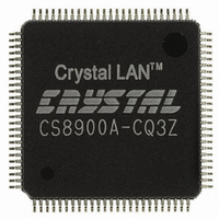
CS8900A-CQ3Z Cirrus Logic Inc, CS8900A-CQ3Z Datasheet - Page 4

CS8900A-CQ3Z
Manufacturer Part Number
CS8900A-CQ3Z
Description
IC LAN ETHERNET CTLR 3V 100LQFP
Manufacturer
Cirrus Logic Inc
Type
Single Chipr
Specifications of CS8900A-CQ3Z
Package / Case
100-LQFP
Controller Type
Ethernet Controller (IEEE 802.3)
Interface
ISA-BUS
Voltage - Supply
3V, 5V
Current - Supply
95mA
Operating Temperature
0°C ~ 70°C
Mounting Type
Surface Mount
Ethernet Connection Type
10BASE- 2 or 10BASE- 5 or 10BASE- F or 10BASE- T
Minimum Operating Temperature
0 C
Mounting Style
SMD/SMT
Product
Ethernet Controllers
Standard Supported
IEEE 802.3
Data Rate
10 Mbps
Supply Voltage (max)
6 V
Supply Voltage (min)
- 0.3 V
Supply Current (max)
+/- 10 mA
Maximum Operating Temperature
+ 70 C
Lead Free Status / RoHS Status
Lead free / RoHS Compliant
For Use With
598-1163 - KIT EVAL FOR CS8900A
Lead Free Status / Rohs Status
Lead free / RoHS Compliant
Other names
598-1127
Available stocks
Company
Part Number
Manufacturer
Quantity
Price
Company:
Part Number:
CS8900A-CQ3Z
Manufacturer:
CIRRUS
Quantity:
16 572
Company:
Part Number:
CS8900A-CQ3Z
Manufacturer:
CIRRUSLOGIC92
Quantity:
1 900
Company:
Part Number:
CS8900A-CQ3Z
Manufacturer:
Cirrus Logic Inc
Quantity:
10 000
Part Number:
CS8900A-CQ3Z
Manufacturer:
CIRRUS
Quantity:
20 000
Company:
Part Number:
CS8900A-CQ3ZR
Manufacturer:
Cirrus Logic Inc
Quantity:
10 000
Part Number:
CS8900A-CQ3ZR
Manufacturer:
CIRRUS
Quantity:
20 000
4
4.0 PACKETPAGE ARCHITECTURE..........................................................................................41
3.11 10BASE-T Transceiver ..................................................................................................36
3.12 Attachment Unit Interface (AUI) ....................................................................................39
3.13 External Clock Oscillator ...............................................................................................40
4.1 PacketPage Overview .....................................................................................................41
4.2 PacketPage Memory Map ...............................................................................................42
4.3 Bus Interface Registers ...................................................................................................44
4.4 Status and Control Registers ..........................................................................................49
4.5 Initiate Transmit Registers ...............................................................................................69
4.6 Address Filter Registers ..................................................................................................71
4.7 Receive and Transmit Frame Locations ..........................................................................72
4.8 Eight and Sixteen Bit Transfers .......................................................................................72
4.9 Memory Mode Operation .................................................................................................73
4.10 I/O Space Operation ......................................................................................................75
3.10.4 Interface Selection ............................................................................................36
3.11.1 10BASE-T Filters ..............................................................................................37
3.11.2 Transmitter .......................................................................................................37
3.11.3 Receiver ...........................................................................................................37
3.11.4 Link Pulse Detection .........................................................................................38
3.11.5 Receive Polarity Detection and Correction .......................................................38
3.11.6 Collision Detection ............................................................................................39
3.12.1 AUI Transmitter .................................................................................................39
3.12.2 AUI Receiver ....................................................................................................39
3.12.3 Collision Detection ............................................................................................39
4.1.1 Integrated Memory .............................................................................................41
4.1.2 Bus Interface Registers ......................................................................................41
4.1.3 Status and Control Registers ..............................................................................41
4.1.4 Initiate Transmit Registers ..................................................................................41
4.1.5 Address Filter Registers .....................................................................................41
4.1.6 Receive and Transmit Frame Locations .............................................................41
4.4.1 Configuration and Control Registers ...................................................................49
4.4.2 Status and Event Registers ................................................................................49
4.4.3 Status and Control Bit Definitions .......................................................................50
4.4.4 Status and Control Register Summary ...............................................................51
4.7.1 Receive PacketPage Locations ..........................................................................72
4.7.2 Transmit Locations .............................................................................................72
4.8.1 Transferring Odd-Byte-Aligned Data ..................................................................73
4.8.2 Random Access to CS8900A Memory ...............................................................73
4.9.1 Accesses in Memory Mode .................................................................................73
4.9.2 Configuring the CS8900A for Memory Mode ......................................................74
4.9.3 Basic Memory Mode Transmit ............................................................................74
4.9.4 Basic Memory Mode Receive .............................................................................75
4.9.5 Polling the CS8900A in Memory Mode ...............................................................75
4.10.1 Receive/Transmit Data Ports 0 and 1 ...............................................................75
3.10.4.1 10BASE-T Only .................................................................................36
3.10.4.2 AUI Only ............................................................................................36
3.10.4.3 Auto-Select ........................................................................................36
3.11.3.1 Squelch Circuit ...................................................................................37
3.11.3.2 Extended Range ................................................................................38
4.4.3.1 Act-Once Bits .......................................................................................50
4.4.3.2 Temporal Bits .......................................................................................50
4.4.3.3 Interrupt Enable Bits and Events .........................................................50
4.4.3.4 Accept Bits ...........................................................................................51
CIRRUS LOGIC PRODUCT DATASHEET
Crystal LAN™ Ethernet Controller
CS8900A
DS271F5


