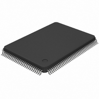
DS21Q43AT Maxim Integrated Products, DS21Q43AT Datasheet - Page 36

DS21Q43AT
Manufacturer Part Number
DS21Q43AT
Description
IC FRAMER E1 QUAD 5V IND 128TQFP
Manufacturer
Maxim Integrated Products
Datasheet
1.DS21Q43AT.pdf
(60 pages)
Specifications of DS21Q43AT
Controller Type
E1 Framer
Interface
Parallel/Serial
Voltage - Supply
4.5 V ~ 5.5 V
Current - Supply
32mA
Operating Temperature
0°C ~ 70°C
Mounting Type
Surface Mount
Package / Case
128-TQFP, 128-VQFP
Dc
0319
Lead Free Status / RoHS Status
Contains lead / RoHS non-compliant
Available stocks
Company
Part Number
Manufacturer
Quantity
Price
Part Number:
DS21Q43AT
Manufacturer:
MAXIM/美信
Quantity:
20 000
Part Number:
DS21Q43AT+
Manufacturer:
MAXIM/美信
Quantity:
20 000
Part Number:
DS21Q43ATN
Manufacturer:
DALLAS
Quantity:
20 000
7.0 SIGNALING OPERATION
The Channel Associated Signaling (CAS) bits embedded in the E1 stream can be extracted from the
receive stream and inserted into the transmit stream by the DS21Q43A. Each of the 30 channels has four
signaling bits (A/B/C/D) associated with it. The numbers in parenthesis () are the channel associated with
a particular signaling bit. The channel numbers have been assigned as described in the ITU/CCITT
documents. For example, channel 1 is associated with timeslot 1 and channel 30 is associated with
timeslot 31. There is a set of 16 registers for the receive side (RS1 to RS16) and 16 registers on the
transmit side (TS1 to TS16). The signaling registers are detailed below.
RS1 TO RS16: RECEIVE SIGNALING REGISTERS (Address=30 to 3F Hex)
(MSB)
Each Receive Signaling Register (RS1 to RS16) reports the incoming signaling bits from two timeslots.
The bits in the Receive Signaling Registers are updated on multiframe boundaries so the user can utilize
the Receive Multiframe Interrupt in the Receive Status Register 2 (SR2.7) to know when to retrieve the
signaling bits. The user has a full 2 ms to retrieve the signaling bits before the data is lost. The RS
registers are updated under all conditions. Their validity should be qualified by checking for
synchronization at the CAS level. In CCS signaling mode, RS1 to RS16 can also be used to extract
A(10)
A(11)
A(12)
A(13)
A(14)
A(15)
A(1)
A(2)
A(3)
A(4)
A(5)
A(6)
A(7)
A(8)
A(9)
0
SYMBOL
D(30)
A(1)
X
Y
B(10)
B(11)
B(12)
B(13)
B(14)
B(15)
B(1)
B(2)
B(3)
B(4)
B(5)
B(6)
B(7)
B(8)
B(9)
0
POSITION
RS1.0/1/3
RS16.0
RS1.2
RS2.7
C(10)
C(11)
C(12)
C(13)
C(14)
C(15)
C(1)
C(2)
C(3)
C(4)
C(5)
C(6)
C(7)
C(8)
C(9)
0
NAME AND DESCRIPTION
Spare Bits.
Remote Alarm Bit (integrated and reported in SR1.6).
Signaling Bit A for Channel 1.
Signaling Bit D for Channel 30.
D(10)
D(11)
D(12)
D(13)
D(14)
D(15)
D(1)
D(2)
D(3)
D(4)
D(5)
D(6)
D(7)
D(8)
D(9)
0
36 of 60
A(16)
A(17)
A(18)
A(19)
A(20)
A(21)
A(22)
A(23)
A(24)
A(25)
A(26)
A(27)
A(28)
A(29)
A(30)
X
B(16)
B(17)
B(18)
B(19)
B(20)
B(21)
B(22)
B(23)
B(24)
B(25)
B(26)
B(27)
B(28)
B(29)
B(30)
Y
C(16)
C(17)
C(18)
C(19)
C(20)
C(21)
C(22)
C(23)
C(24)
C(25)
C(26)
C(27)
C(28)
C(29)
C(30)
X
D(16)
D(17)
D(18)
D(19)
D(20)
D(21)
D(22)
D(23)
D(24)
D(25)
D(26)
D(27)
D(28)
D(29)
D(30)
(LSB)
X
RS11 (3A)
RS14 (3D)
RS12 (3B)
RS13 (3C)
RS15 (3E)
RS16 (3F)
RS10 (36)
RS1 (30)
RS2 (31)
RS3 (32)
RS4 (33)
RS5 (34)
RS6 (35)
RS7 (36)
RS8 (34)
RS9 (35)
DS21Q43A


