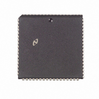
DP8390DV National Semiconductor, DP8390DV Datasheet - Page 10

DP8390DV
Manufacturer Part Number
DP8390DV
Description
IC CTRLR NETWORK IN (NIC)68PLCC
Manufacturer
National Semiconductor
Datasheet
1.DP8390DN.pdf
(56 pages)
Specifications of DP8390DV
Controller Type
Network Interface Controller (NIC)
Voltage - Supply
5V
Current - Supply
40mA
Mounting Type
Surface Mount
Package / Case
68-LCC (J-Lead)
Lead Free Status / RoHS Status
Contains lead / RoHS non-compliant
Operating Temperature
-
Interface
-
Other names
*DP8390DV
Available stocks
Company
Part Number
Manufacturer
Quantity
Price
Company:
Part Number:
DP8390DV
Manufacturer:
NSC
Quantity:
5 510
Company:
Part Number:
DP8390DV
Manufacturer:
SIEMENS
Quantity:
5 510
Part Number:
DP8390DV
Manufacturer:
NS/国半
Quantity:
20 000
Company:
Part Number:
DP8390DV NS32490DV
Manufacturer:
NSC
Quantity:
5 510
Company:
Part Number:
DP8390DV NS32490DV
Manufacturer:
SUPERTEX
Quantity:
5 510
Company:
Part Number:
DP8390DV/NS32490DV
Manufacturer:
NSC
Quantity:
5 510
7 0 Packet Reception
10 Take the NIC out of loopback This is done by writing the
11 If the ‘‘Resend’’ variable is set to a 1 reset the ‘‘Re-
Note If Remote DMA is not being used the NIC does not need to be started
END OF PACKET OPERATIONS
At the end of the packet the NIC determines whether the
received packet is to be accepted or rejected It either
branches to a routine to store the Buffer Header or to anoth-
er routine that recovers the buffers used to store the packet
SUCCESSFUL RECEPTION
If the packet is successfully received as shown the DMA is
restored to the first buffer used to store the packet (pointed
6 Place the NIC in either mode 1 or mode 2 loopback This
7 Issue the START command to the NIC This can be ac-
8 Remove one or more packets from the receive buffer
9 Reset the overwrite warning (OVW overflow) bit in the
Termination of Received Packet Packet Accepted
then the packet will essentially be lost and re-transmit-
ted only after a time-out takes place in the upper level
software By determining that the packet was lost at the
driver level a transmit command can be reissued to the
NIC once the overflow routine is completed (as in step
11) Also it is possible for the NIC to defer indefinitely
when it is stopped on a busy network Step 5 also allevi-
ates this problem Step 5 is essential and should not be
omitted from the overflow routine in order for the NIC to
operate correctly
can be accomplished by setting bits D2 and D1 of the
Transmit Configuration Register to ‘‘0 1’’ or ‘‘1 0’’ re-
spectively
complished by writing 22H to the Command Register
This is necessary to activate the NIC’s Remote DMA
channel
ring
Interrupt Status Register
Transmit Configuration Register with the value it con-
tains during normal operation (Bits D2 and D1 should
both be programmed to 0 )
send’’ variable and reissue the transmit command This
is done by writing a value of 26H to the Command Reg-
ister If the ‘‘Resend’’ variable is 0 nothing needs to be
done
before packets can be removed from the receive buffer ring Hence
step 8 could be done before step 7
(Continued)
TL F 8582– 10
10
to by the Current Page Register) The DMA then stores the
Receive Status a Pointer to where the next packet will be
stored (Buffer 4) and the number of received bytes Note
that the remaining bytes in the last buffer are discarded and
reception of the next packet begins on the next empty 256-
byte buffer boundary The Current Page Register is then
initialized to the next available buffer in the Buffer Ring (The
location of the next buffer had been previously calculated
and temporarily stored in an internal scratchpad register )
BUFFER RECOVERY FOR REJECTED PACKETS
If the packet is a runt packet or contains CRC or Frame
Alignment errors it is rejected The buffer management log-
ic resets the DMA back to the first buffer page used to store
the packet (pointed to by CURR) recovering all buffers that
had been used to store the rejected packet This operation
will not be performed if the NIC is programmed to accept
either runt packets or packets with CRC or Frame Alignment
errors The received CRC is always stored in buffer memory
after the last byte of received data for the packet
Error Recovery
If the packet is rejected as shown the DMA is restored by
the NIC by reprogramming the DMA starting address point-
ed to by the Current Page Register
REMOVING PACKETS FROM THE RING
Packets are removed from the ring using the Remote DMA
or an external device When using the Remote DMA the
Send Packet command can be used This programs the Re-
mote DMA to automatically remove the received packet
pointed to by the Boundary Pointer At the end of the trans-
fer the NIC moves the Boundary Pointer freeing additional
buffers for reception The Boundary Pointer can also be
moved manually by programming the Boundary Register
Care should be taken to keep the Boundary Pointer at least
one buffer behind the Current Page Pointer
The following is a suggested method for maintaining the
Receive Buffer Ring pointers
1 At initialization set up a software variable (next pkt) to
2 When initializing the NIC set
indicate where the next packet will be read At the begin-
ning of each Remote Read DMA operation the value of
next pkt will be loaded into RSAR0 and RSAR1
BNDRY
CURR
next pkt
Termination of Received Packet Packet Rejected
e
e
PSTART
e
PSTART
PSTART
a
1
a
1
TL F 8582– 13


