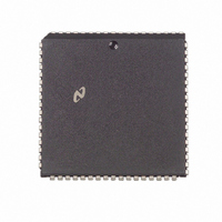
DP8390DV National Semiconductor, DP8390DV Datasheet - Page 6

DP8390DV
Manufacturer Part Number
DP8390DV
Description
IC CTRLR NETWORK IN (NIC)68PLCC
Manufacturer
National Semiconductor
Datasheet
1.DP8390DN.pdf
(56 pages)
Specifications of DP8390DV
Controller Type
Network Interface Controller (NIC)
Voltage - Supply
5V
Current - Supply
40mA
Mounting Type
Surface Mount
Package / Case
68-LCC (J-Lead)
Lead Free Status / RoHS Status
Contains lead / RoHS non-compliant
Operating Temperature
-
Interface
-
Other names
*DP8390DV
Available stocks
Company
Part Number
Manufacturer
Quantity
Price
Company:
Part Number:
DP8390DV
Manufacturer:
NSC
Quantity:
5 510
Company:
Part Number:
DP8390DV
Manufacturer:
SIEMENS
Quantity:
5 510
Part Number:
DP8390DV
Manufacturer:
NS/国半
Quantity:
20 000
Company:
Part Number:
DP8390DV NS32490DV
Manufacturer:
NSC
Quantity:
5 510
Company:
Part Number:
DP8390DV NS32490DV
Manufacturer:
SUPERTEX
Quantity:
5 510
Company:
Part Number:
DP8390DV/NS32490DV
Manufacturer:
NSC
Quantity:
5 510
5 0 Pin Descriptions
BUS INTERFACE PINS (Continued)
Symbol
PWR
RACK
BSCK
NETWORK INTERFACE PINS
COL
RXD
CRS
RXC
LBK
TXD
TXC
TXE
POWER
V
GND
6 0 Direct Memory Access Control (DMA)
The DMA capabilities of the NIC greatly simplify use of the
DP8390D in typical configurations The local DMA channel
transfers data between the FIFO and memory On transmis-
sion the packet is DMA’d from memory to the FIFO in
bursts Should a collision occur (up to 15 times) the packet
is retransmitted with no processor intervention On recep-
tion packets are DMAed from the FIFO to the receive buffer
ring (as explained below)
A remote DMA channel is also provided on the NIC to ac-
complish transfers between a buffer memory and system
memory The two DMA channels can alternatively be com-
bined to form a single 32-bit address with 8- or 16-bit data
DUAL DMA CONFIGURATION
An example configuration using both the local and remote
DMA channels is shown below Network activity is isolated
CC
DIP Pin No
27
26
25
40
39
38
37
35
34
33
32
36
13
Function
(Continued)
O
O
O
O
I
I
I
I
I
I
I
PORT WRITE Strobe used to latch data from the NIC into external latch for
transfer to host memory during Remote Read transfers The rising edge of PWR
coincides with the presence of valid data on the local bus
READ ACKNOWLEDGE Indicates that the system DMA or host CPU has read
the data placed in the external latch by the NIC The NIC will begin a read cycle
to update the latch
This clock is used to establish the period of the DMA memory cycle Four clock
cycles (t1 t2 t3 t4) are used per DMA cycle DMA transfers can be extended by
one BSCK increments using the READY input
COLLISION DETECT This line becomes active when a collision has been
detected on the coaxial cable During transmission this line is monitored after
preamble and synch have been transmitted At the end of each transmission this
line is monitored for CD heartbeat
RECEIVE DATA Serial NRZ data received from the ENDEC clocked into the
NIC on the rising edge of RXC
CARRIER SENSE This signal is provided by the ENDEC and indicates that
carrier is present This signal is active high
RECEIVE CLOCK Re-synchronized clock from the ENDEC used to clock data
from the ENDEC into the NIC
LOOPBACK This output is set high when the NIC is programmed to perform a
loopback through the StarLAN ENDEC
TRANSMIT DATA Serial NRZ Data output to the ENDEC The data is valid on
the rising edge of TXC
TRANSMIT CLOCK This clock is used to provide timing for internal operation
and to shift bits out of the transmit serializer TXC is nominally a 1 MHz clock
provided by the ENDEC
TRANSMIT ENABLE This output becomes active when the first bit of the
packet is valid on TXD and goes low after the last bit of the packet is clocked out
of TXD This signal connects directly to the ENDEC This signal is active high
between these pins It is essential to provide a path to ground for the GND pin
with the lowest possible impedance
a
5V DC is required It is suggested that a decoupling capacitor be connected
6
on a local bus where the NIC’s local DMA channel per-
forms burst transfers between the buffer memory and the
NIC’s FIFO The Remote DMA transfers data between the
buffer memory and the host memory via a bidirectional I O
port The Remote DMA provides local addressing capability
and is used as a slave DMA by the host Host side address-
ing must be provided by a host DMA or the CPU The NIC
allows Local and Remote DMA operations to be interleaved
SINGLE CHANNEL DMA OPERATION
If desirable the two DMA channels can be combined to
provide a 32-bit DMA address The upper 16 bits of the 32-
bit address are static and are used to point to a 64k byte (or
32k word) page of memory where packets are to be re-
ceived and transmitted
Description


