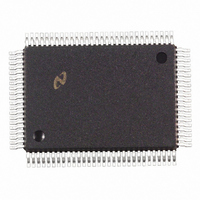
DP83840AVCE National Semiconductor, DP83840AVCE Datasheet - Page 11

DP83840AVCE
Manufacturer Part Number
DP83840AVCE
Description
IC ETHERNET PHYS LAYER 100-PQFP
Manufacturer
National Semiconductor
Datasheet
1.DP83840AVCE.pdf
(89 pages)
Specifications of DP83840AVCE
Controller Type
Ethernet Controller, 10Base-T
Interface
IEEE 802.3af
Voltage - Supply
4.75 V ~ 5.25 V
Current - Supply
335mA
Operating Temperature
0°C ~ 70°C
Mounting Type
Surface Mount
Package / Case
100-MQFP, 100-PQFP
Lead Free Status / RoHS Status
Contains lead / RoHS non-compliant
Other names
*DP83840AVCE
Available stocks
Company
Part Number
Manufacturer
Quantity
Price
Company:
Part Number:
DP83840AVCE
Manufacturer:
Texas Instruments
Quantity:
10 000
Part Number:
DP83840AVCE
Manufacturer:
NS/国半
Quantity:
20 000
Version A
2.0 Pin Description
2.6 LED INTERFACE
These outputs can be used to drive LEDs directly, or can be used to provide status information to a network
management device. Refer to Figure 12 for the LED connection diagram. Refer to section 2.2 for a description of how to
generate LED indication of 100 Mb/s mode. Note that these outputs are standard CMOS voltage drivers and not
open-drain.
LED1
LED2
LED3
LED4
LED5
Signal Name
I = TTL/CMOS input
Type
O, J
O, J
O, J
O, J
O, J
O = TTL/CMOS output
(Continued)
Pin #
42
41
38
37
36
TRANSMIT LED: Indicates the presence of transmit activity (TXE asserted) for 10
Mb/s and 100 Mb/s operation. Active low.
If bit 2 (LED1_MODE) of the PCS Configuration Register (address 17h) is set
high, then the LED1 pin function is changed to indicate the status of the
Disconnect Function as defined by the state of bit 5 (CON_STATUS) in the PHY
address register (address 19h).
The DP83840A incorporates a “monostable” function on the LED1 output. This
ensures that even minimum size packets generate adequate LED ON time
(approximately 50ms) for visibility.
RECEIVE LED: Indicates the presence of any receive activity (CRS active) for 10
Mb/s and 100 Mb/s operation. Active low.
The DP83840A incorporates a “monostable” function on the LED2 output. This
ensures that even minimum size packets generate adequate LED ON time
(approximately 50ms) for visibility.
LINK LED: Indicates Good Link status for 10 Mb/s and 100 Mb/s operation. Active
low.
100 Mb/s Link is established as a result of the assertion of the Signal Detect input
to the DP83840A. LED3 will assert after SD has remained asserted for a minimum
of 500 s. LED3 will deassert immediately following the deassertion of Signal
Detect.
10 Mb/s Link is established as a result of the reception of at least seven
consecutive normal Link Pulses or the reception of a valid 10BASE-T packet
which will cause the assertion of LED3. LED3 will deassert in accordance with the
Link Loss Timer as specified in 802.3.
POLARITY/FULL DUPLEX LED: Indicates Good Polarity status for 10 Mb/s
operation. Can be configured to Indicate Full Duplex mode status for 10 Mb/s or
100 Mb/s operation. Active low.
The DP83840A automatically compensates for polarity inversion. Polarity
inversion is indicated by the assertion of LED4.
If bit 1 (LED4_MODE) in the PCS Configuration Register (address 17h) is set
high, the LED4 pin function is changed to indicate Full Duplex mode status for 10
Mb/s and 100 Mb/s operation.
COLLISION LED: Indicates the presence of collision activity for 10 Mb/s and 100
Mb/s Half Duplex operation. This LED has no meaning for 10 Mb/s or 100 Mb/s
Full Duplex operation and will remain deasserted. Active low.
Z = TRI-STATE output
11
J = IEEE 1149.1 pin
Description
National Semiconductor


