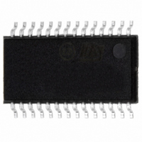
ST7540TR STMicroelectronics, ST7540TR Datasheet - Page 22

ST7540TR
Manufacturer Part Number
ST7540TR
Description
IC TXRX FSK POWER LINE 28-TSSOP
Manufacturer
STMicroelectronics
Type
Transceiverr
Datasheet
1.ST7540TR.pdf
(44 pages)
Specifications of ST7540TR
Number Of Drivers/receivers
1/1
Voltage - Supply
5 V ~ 9 V
Mounting Type
Surface Mount
Package / Case
28-TSSOP Exposed Pad, 28-eTSSOP, 28-HTSSOP
For Use With
497-5485 - BOARD EVAL ST7540 PWR LINE TXRX
Lead Free Status / RoHS Status
Lead free / RoHS Compliant
Protocol
-
Lead Free Status / Rohs Status
Compliant
Other names
497-5528-2
Available stocks
Company
Part Number
Manufacturer
Quantity
Price
Company:
Part Number:
ST7540TR
Manufacturer:
FENGHUA
Quantity:
400 000
Company:
Part Number:
ST7540TR
Manufacturer:
ST
Quantity:
2 100
Part Number:
ST7540TR
Manufacturer:
ST
Quantity:
20 000
Functional description
6.5.2
22/44
Control register access
The communication with ST7540 Control Register is always synchronous. The access is
achieved using the same lines of the Mains interface (RxD, TxD, RxTx and CLR/T) plus
REG_DATA Line.
With REG_DATA = 1 and RxTx = 0, the data present on TxD are loaded into the Control
Register MSB first. The ST7540 samples the TxD line on CLR/T rising edges. The control
Register content is updated at the end of the register access section (REG_DATA falling
edge).
In Normal Control Register mode (Control Register bit 21 = ”0”, see
24 bits are transferred to ST7540 only latest 24 bits are stored inside the Control Register. If
less than 24 bits are transferred to ST7540 the Control Register writing is aborted.
In order to avoid undesired Control Register writings caused by REG_DATA line fluctuations
(for example because of surge or burst on mains), in Extended Control Register mode
(Control Register bit 21 = ”1” see
ST7540 in order to properly write the Control Register, otherwise writing is aborted. If 24 bits
are transferred, only the first 24 Control Register bits (from 23 to 0) are written.
With REG_DATA = 1 and RxTx = 1, the content of the Control Register is sent on RxD port.
The Data on RxD are stable on CLR/T rising edges MSB First. In Normal Control Register
mode 24 bits are transferred from ST7540 to the Host. In Extended Control Register mode
24 or 48 bits are transferred from ST7540 to the Host depending on content of Control
Register bit 18 (with bit 18 = ”0” the first 24 bits are transferred, otherwise all 48 bits are
transferred, see
Figure 9.
Figure 10. data reception
REG_DATA
REG_DATA
CLR_T
CLR_T
RxTx
RxTx
RxD
RxD
TxD
T
T
DS
DS
T
T
DH
DH
Data reception
Table
T
12).
T
CR
CR
➨
➨
T
CR
control register write
control register read
T
T
Table
CC
CC
T
DS
12) exactly 24 or 48 bits must be transferred to
BIT23
BIT23
T
S
T
H
T
DH
BIT22
BIT22
➨
➨
data reception timing diagram
data reception timing diagram
T
CR
T
T
CR
Table
CR
T
T
CC
CC
12) if more than
T
D03IN1404
T
B
ST7540
D03IN1403
B


