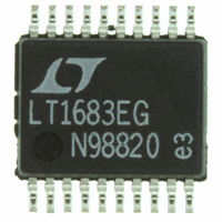
LTC1562CG#PBF Linear Technology, LTC1562CG#PBF Datasheet - Page 11

LTC1562CG#PBF
Manufacturer Part Number
LTC1562CG#PBF
Description
IC FILTER UNIV RC QUAD LN 20SSOP
Manufacturer
Linear Technology
Datasheet
1.LTC1562CGPBF.pdf
(28 pages)
Specifications of LTC1562CG#PBF
Filter Type
Universal, Continuous-Time
Frequency - Cutoff Or Center
150kHz
Number Of Filters
4
Max-order
8th
Voltage - Supply
4.75 V ~ 10.5 V, ±4.75 V ~ 5.25 V
Mounting Type
Surface Mount
Package / Case
20-SSOP
Lead Free Status / RoHS Status
Lead free / RoHS Compliant
Available stocks
Company
Part Number
Manufacturer
Quantity
Price
APPLICATIONS
external component Z
This component must of course be rated to sustain the
magnitude of voltage imposed on it.
Lowpass “T” Input Circuit
The virtual ground INV input in the Operational Filter block
provides a means for adding an “extra” lowpass pole to
any resistor-input application (such as the basic lowpass,
Figure 5, or bandpass, Figure 6a). The resistor that would
otherwise form Z
to ground added, forming an R-C-R “T” network (Figure
9). This adds an extra, independent real pole at a fre-
quency:
where C
parallel combination of the two input resistors R
R
scribed series total value R
described above. The parallel value R
arbitrarily (to R
convenient standard capacitor value for C
the new pole with R
The procedure therefore is to begin with the target extra
pole frequency f
gain requirement. Select a capacitor value C
= 1/(2 f
R
value R
be found directly from the expression:
INB
INA
f
2
1
P
. This pair of resistors must normally have a pre-
R
and R
IN
P
2
P
T
and the series value R
C
is the new external capacitor and R
V
T
R C
2
1
IN
1
) is no greater than R
INB
P T
Figure 9. Lowpass “T” Input Circuit
R
that will simultaneously have the parallel
P
IN
IN
R
. Determine the series value R
IN
INA
2
/4 or less) which allows choosing a
U
–
is split into two parts and a capacitor
P
.
IN
4
R R
, usually a resistor or capacitor.
C
R
INFORMATION
T
INB
IN P
U
IN
INV
IN
to set the filter’s gain as
1/4 LTC1562
2nd ORDER
. Such R
IN
V1
W
/4, and then choose
P
R
Q
can however be set
V2
T
INA
R2
and fine tuning
1562 F09
T
and R
such that R
IN
U
from the
P
INA
INB
is the
and
can
P
A practical limitation of this technique is that the C
tor values that tend to be required (hundreds or thousands
of pF) can destabilize the op amp in Figure 3 if R
small, leading to AC errors such as Q enhancement. For this
reason, when R
larger of the two should be placed in the R
Highpass “T” Input Circuit
A method similar to the preceding technique adds an
“extra” highpass pole to any capacitor-input application
(such as the bandpass of Figure 6b or the highpass of
Figure 7). This method splits the input capacitance C
two series parts C
between them (Figure 10). This adds an extra 1st order
highpass corner with a zero at DC and a pole at the
frequency:
where C
two capacitors. At the same time, the total series capaci-
tance C
Basic Highpass). For a given series value C
value C
The procedure then is to begin with the target corner (pole)
frequency f
requirement (for example, C
Select a resistor value R
least 4C
have the parallel value C
C
INA
f
2
1
P
C
and C
P
P
IN
IN
2
P
can still be set arbitrarily (to 4C
, and select C
= C
will control the filter’s gain parameter (H
2
1
INB
V
R C
P
IN
1
Figure 10. Highpass “T” Input Circuit
. Determine the series value C
T P
INA
C
can be found directly from the expression:
P
C
INA
INA
2
+ C
INA
–
and R
INB
and C
4
R
INA
C C
T
C
is the parallel combination of the
IN P
T
INB
P
and C
IN
such that C
INB
and the series value C
IN
B are unequal, preferably the
INV
, with a resistor R
= H
1/4 LTC1562
2nd ORDER
INB
H
V1
(159pF) for a highpass).
that will simultaneously
R
Q
P
V2
= 1/(2 R
R2
IN
IN
LTC1562
1562 F10
INB
IN
or greater).
from the gain
, the parallel
T
position.
to ground
INB
T
T
IN
f
11
capaci-
P
. Such
IN
) is at
is too
1562fa
H
into
in


