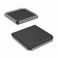
HSP43220JC-25Z Intersil, HSP43220JC-25Z Datasheet - Page 4

HSP43220JC-25Z
Manufacturer Part Number
HSP43220JC-25Z
Description
IC DECIMATING DGTL FILTER 84PLCC
Manufacturer
Intersil
Datasheet
1.HSP43220JC-25Z.pdf
(21 pages)
Specifications of HSP43220JC-25Z
Filter Type
Digital
Number Of Filters
4
Voltage - Supply
4.75 V ~ 5.25 V
Mounting Type
Surface Mount
Package / Case
84-PLCC
Lead Free Status / RoHS Status
Lead free / RoHS Compliant
Frequency - Cutoff Or Center
-
Max-order
-
Available stocks
Company
Part Number
Manufacturer
Quantity
Price
Integrator Section
The data from the shifter goes to the Integrator section.
This is a cascade of 5 integrator (or accumulator) stages,
which implement a low pass filter. Each accumulator is
implemented as an adder followed by a register in the feed
forward path. The integrator is clocked by the sample clock,
CK_IN as shown in Figure 2. The bit width of each integrator
stage goes from 66 bits at the first integrator down to 26 bits
at the output of the fifth integrator. Bit truncation is performed
at each integrator stage because the data in the integrator
stages is being accumulated and thus is growing, therefore
the lower bits become insignificant, and can be truncated
without losing significant data.
There are three signals that control the integrator section;
they are H_STAGES, H_BYP and RESET. In Figure 2 these
control signals have been decoded and are labelled
INT_EN1 - INT_EN5. The order of the filter is loaded via the
FROM
SHIFTER
CK
CK_DEC
CK_IN
DATA
IN
IN
66
H_GROWTH
16
A0-1
ISTART
∑
6
INPUT
REG
INT_EN5
REGISTER LOGIC
MUX
CONTROL
INT_EN1-5
16
REG
WR
H_GROWTH
0
SHIFTER
5
DATA
63
4
CS
6
COMB_EN1-5
C_BUS
66
∑
INT_EN4
5
FIGURE 1. HIGH ORDER DECIMATION FILTER FIGURE
MUX
H_DRATE
INTEGRATOR
H_BYP
INT_EN1-5
REG
0
5
53
HDF FILTER SECTION
CK_IN
FIGURE 2. INTEGRATOR
26
∑
DIVIDER
CLOCK
CK DEC
INT_EN3
HSP43220
RESET
DEC
REG
MUX
RESET
REG
26
0
control bus and is called H_STAGES. H_STAGES is
decoded to provide the enables for each integrator stage.
When a given integrator stage is selected, the feedback path
is enabled and the integrator accumulates the current data
sample with the previous sum. The integrator section can be
put in bypass mode by the H_BYP bit. When H_BYP or
RESET is asserted, the feedback paths in all integrator
stages are cleared.
Decimation Register
The output of the Integrator section is latched into the
Decimation Register by CK_DEC. The output of the
Decimation register is cleared when RESET is asserted. The
HDF decimation rate = H_DRATE +1, which is defined as
H
COMB FILTER
COMB_EN1-5
43
DEC
ISTART
5
for convenience.
RESET
∑
INT_EN2
MUX
19
REG
CK_IN
0
START
LOGIC
ROUND
35
ASTARTIN
16
∑
INT_EN1
MUX
RESET
REG
REG
STARTIN
STARTOUT
TO FIR
16
TO FIR
0
26
TO
DECIMATION
REGISTER
October 10, 2008
FN2486.10


