AT42QT1040-MMH Atmel, AT42QT1040-MMH Datasheet - Page 25
AT42QT1040-MMH
Manufacturer Part Number
AT42QT1040-MMH
Description
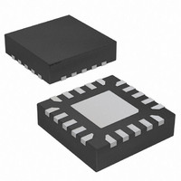
IC TOUCH SENSOR 4KEY 20-VQFN
Manufacturer
Atmel
Series
QTouch™r
Type
Resistiver
Specifications of AT42QT1040-MMH
Touch Panel Interface
4, 2-Wire
Number Of Inputs/keys
4 Key
Data Interface
I²C, Serial
Data Rate/sampling Rate (sps, Bps)
200k
Voltage Reference
Internal
Voltage - Supply
1.8 V ~ 5.5 V
Current - Supply
10mA
Operating Temperature
-40°C ~ 85°C
Mounting Type
Surface Mount
Package / Case
20-VQFN Exposed Pad, 20-HVQFN, 20-SQFN, 20-DHVQFN
Output Type
Logic
Input Type
Logic
Supply Voltage
1.8 V to 5.5 V
Dimensions
3 mm L x 3 mm W x 0.8 mm H
Output Voltage
0.7 V to 0.8 V
Temperature Range
- 40 C to + 85 C
Termination Style
SMD/SMT
Lead Free Status / RoHS Status
Lead free / RoHS Compliant
Interface
-
Lead Free Status / Rohs Status
Lead free / RoHS Compliant
Other names
AT42QT1040-MMH
AT42QT1040-MMHTR
AT42QT1040-MMHTR
Available stocks
Company
Part Number
Manufacturer
Quantity
Price
Company:

Part Number:
AT42QT1040-MMH
Manufacturer:
FUJITSU
Quantity:
349
Company:
Part Number:
AT42QT1040-MMH
Manufacturer:
Atmel
Quantity:
30 294
Part Number:
AT42QT1040-MMH
Manufacturer:
MICROCHIP/微芯
Quantity:
20 000
Part Number:
AT42QT1040-MMH-T
Manufacturer:
MICROCHIP/微芯
Quantity:
20 000
Part Number:
AT42QT1040-MMHR
Manufacturer:
ATMEL/爱特梅尔
Quantity:
20 000


3.2.5
Touch Sensors Design Guide
Illumination Effects
Figure 3-6.
It is important to note that interconnecting traces should not be run over ground or power planes where
possible, especially when the separation to the plane is small (for example, when the traces and the
ground or power plane are on adjacent layers of a multilayer PCB). Doing so can quickly desensitize the
key. If sensor traces must run close to other foreign signals, avoid tracking them in parallel in order to
reduce the coupling. Where they cross, cross them at 90° for the same reason.
Running interconnections as part of a cable loom is not a good idea in any circumstances. However,
running sensor traces inside a low capacitance coaxial cable can be done as a last resort, but expect low
sensitivity keys.
LEDs that are very close to the sensor should be bypassed as described in
on page
Backlighting can be achieved by using transparent sensor materials or by making a small hole in the
sensor itself to allow light to shine through from behind (see
for simple, low cost backlighting of the key area to back-illuminate a graphic symbol. Properly
constructed, the result will be a very sensitive key even in the middle.
The width of the copper should be at least as wide as the panel is thick to provide adequate coupling; the
electric field penetrates the panel material to “focus” inwards, while being terminated outwards from the
ring by a ground plane. This method works well only if the panel material is thick enough (and with a high
enough
sensitivity will be lost. If the hole in the middle is too big and/or the panel has a low
the fields in the middle will be weak and the key will not function as intended.
Remember, too, that the LED looks like a ground load – and a constant one if you have remembered to
bypass it – and this will further reduce sensitivity.
2-7.
r
) to conduct the fields inwards. Remember to keep the hole small: the larger the hole, the more
Gap of at least ½T
between the two traces
³½T
Spacing of Adjacent Traces
Minimum possible for technology and RC time constant
Example for PCB: 0.2 mm
Self-capacitance Zero-dimensional Sensors
Sensor Trace
Figure 3-7 on page
Section 2.4 “Nearby LEDs”
Sensor Trace
3-6). This method allows
r
and/or is too thin,
10620D–AT42–04/09
3-5
Related parts for AT42QT1040-MMH
Image
Part Number
Description
Manufacturer
Datasheet
Request
R

Part Number:
Description:
DEV KIT FOR AVR/AVR32
Manufacturer:
Atmel
Datasheet:

Part Number:
Description:
INTERVAL AND WIPE/WASH WIPER CONTROL IC WITH DELAY
Manufacturer:
ATMEL Corporation
Datasheet:
Part Number:
Description:
Low-Voltage Voice-Switched IC for Hands-Free Operation
Manufacturer:
ATMEL Corporation
Datasheet:
Part Number:
Description:
MONOLITHIC INTEGRATED FEATUREPHONE CIRCUIT
Manufacturer:
ATMEL Corporation
Datasheet:
Part Number:
Description:
AM-FM Receiver IC U4255BM-M
Manufacturer:
ATMEL Corporation
Datasheet:
Part Number:
Description:
Monolithic Integrated Feature Phone Circuit
Manufacturer:
ATMEL Corporation
Datasheet:
Part Number:
Description:
Multistandard Video-IF and Quasi Parallel Sound Processing
Manufacturer:
ATMEL Corporation
Datasheet:
Part Number:
Description:
High-performance EE PLD
Manufacturer:
ATMEL Corporation
Datasheet:
Part Number:
Description:
8-bit Flash Microcontroller
Manufacturer:
ATMEL Corporation
Datasheet:
Part Number:
Description:
2-Wire Serial EEPROM
Manufacturer:
ATMEL Corporation
Datasheet: