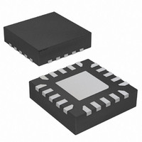
AT42QT1040-MMH Atmel, AT42QT1040-MMH Datasheet - Page 30

AT42QT1040-MMH
Manufacturer Part Number
AT42QT1040-MMH
Description
IC TOUCH SENSOR 4KEY 20-VQFN
Manufacturer
Atmel
Series
QTouch™r
Type
Resistiver
Specifications of AT42QT1040-MMH
Touch Panel Interface
4, 2-Wire
Number Of Inputs/keys
4 Key
Data Interface
I²C, Serial
Data Rate/sampling Rate (sps, Bps)
200k
Voltage Reference
Internal
Voltage - Supply
1.8 V ~ 5.5 V
Current - Supply
10mA
Operating Temperature
-40°C ~ 85°C
Mounting Type
Surface Mount
Package / Case
20-VQFN Exposed Pad, 20-HVQFN, 20-SQFN, 20-DHVQFN
Output Type
Logic
Input Type
Logic
Supply Voltage
1.8 V to 5.5 V
Dimensions
3 mm L x 3 mm W x 0.8 mm H
Output Voltage
0.7 V to 0.8 V
Temperature Range
- 40 C to + 85 C
Termination Style
SMD/SMT
Lead Free Status / RoHS Status
Lead free / RoHS Compliant
Interface
-
Lead Free Status / Rohs Status
Lead free / RoHS Compliant
Other names
AT42QT1040-MMH
AT42QT1040-MMHTR
AT42QT1040-MMHTR
Available stocks
Company
Part Number
Manufacturer
Quantity
Price
Company:
Part Number:
AT42QT1040-MMH
Manufacturer:
FUJITSU
Quantity:
349
Company:
Part Number:
AT42QT1040-MMH
Manufacturer:
Atmel
Quantity:
30 294
Part Number:
AT42QT1040-MMH
Manufacturer:
MICROCHIP/微芯
Quantity:
20 000
Part Number:
AT42QT1040-MMH-T
Manufacturer:
MICROCHIP/微芯
Quantity:
20 000
Part Number:
AT42QT1040-MMHR
Manufacturer:
ATMEL/爱特梅尔
Quantity:
20 000
10620D–AT42–04/09
Self-capacitance Zero-dimensional Sensors
3.3.3
3.3.4
3.3.5
3-10
Secondary Substrate Method
Ground Loading
Illumination Effects
Another option is to form the electrodes on a secondary PCB, flex, or similar substrate. This can then be
bonded to the front panel and interconnected to the control chip by a separate flex tail using an
ACF/ACP connection, or by a tail formed from an extension to the substrate itself. Board-to-board
connectors are also possible.
Figure 3-13. Secondary Substrate Method
Unlike with the planar approach, this style of sensor is less sensitive to ground loading. The reason for
this is that the ground loads (for example, from internal chassis components and other circuits) tend to
be further away from the electrodes and therefore do not desensitize the electrodes so much.
A non-planar approach to sensor construction means that there tends to be a physical separation
between the sensor and front panel. This has the side benefit that it allows LEDs to be incorporated in
the design more easily.
For example, using Philipp spring products as electrode extensions allows an LED to be axially mounted
inside the spring itself (see
touch graphic on the panel above it.
Another popular method of providing illumination is in the form of a light spreader or light guides, as
described for planar construction in
The general rules for LEDs are described in
Front
Panel
Electrode
Substrate
Control
PCB
Figure 3-14 on page
Section 3.2.5 “Illumination Effects” on page
Adhesive
Section 2.4 “Nearby LEDs” on page
3-11), thus giving a good centralized illumination of the
FPC Tail
Connector
FPC/FFC
ACF/ACP
Touch Sensors Design Guide
3-5.
2-7.
Flex Tail


