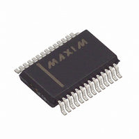
MAX1464AAI+ Maxim Integrated Products, MAX1464AAI+ Datasheet - Page 29

MAX1464AAI+
Manufacturer Part Number
MAX1464AAI+
Description
IC SENSOR SIGNAL COND 28-SSOP
Manufacturer
Maxim Integrated Products
Type
Signal Conditionerr
Datasheet
1.MAX1464AAI.pdf
(47 pages)
Specifications of MAX1464AAI+
Input Type
Analog
Output Type
Logic
Interface
SPI
Current - Supply
890µA
Mounting Type
Surface Mount
Package / Case
28-SSOP
Lead Free Status / RoHS Status
Lead free / RoHS Compliant
Table 3. Module Registers
Table 4. ADC Module Registers
ADC_Control
ADC_Data_1
ADC_Config_1A
ADC_Config_1B
ADC_Data_2
ADC_Config_2A
ADC_Config_2B
ADC_Data_T
ADC_Config_TA
ADC_Config_TB
MODULE
Oscillator
Op Amp
GPIO1
GPIO2
NAME
Power
DOP1
DOP2
Timer
ADC
NAME
ADC_Config_1A
ADC_Config_1B
ADC_Config_2A
ADC_Config_2B
ADC_Config_TA
ADC_Config_TB
Opamp_Config
GPIO1_Control
GPIO2_Control
DOP1_Control
DOP2_Control
DOP1_Config
DOP2_Config
ADC_Control
OSC_Control
ADC_Data_1
ADC_Data_2
ADC_Data_T
TMR_Control
TMR_Config
DOP1_Data
DOP2_Data
REGISTER
PO_Control
______________________________________________________________________________________
NAME
Low-Power, Low-Noise Multichannel
ADDRESS
00h
01h
02h
03h
04h
05h
06h
07h
08h
09h
ADDRESS
00h
01h
02h
03h
04h
05h
06h
07h
08h
09h
10h
11h
12h
13h
14h
15h
20h
21h
30h
31h
32h
40h
41h
Initiate conversions and set signal source.
Result of ADC conversion on channel 1 input.
Settings for channel 1 input and conversion.
Settings for channel 1 input and conversion.
Result of ADC conversion on channel 2 input.
Settings for channel 2 input and conversion.
Settings for channel 2 input and conversion.
Result of ADC conversion on temperature input.
Settings for temperature input and conversion.
Settings for temperature input and conversion.
Initiate conversions and select ADC input.
Result of ADC conversion on channel 1 input.
Settings for channel 1 input and conversion.
Settings for channel 1 input and conversion.
Result of ADC conversion on channel 2 input.
Settings for channel 2 input and conversion.
Settings for channel 2 input and conversion.
Result of ADC conversion on temperature input.
Settings for temperature input and conversion.
Settings for temperature input and conversion.
Input setting for the analog DAC and digital PWM outputs.
Enable and reference selection.
Select DAC or PWM output.
Input setting for the analog DAC and digital PWM outputs.
Enable and reference selection.
Select DAC or PWM output.
Initiate timer.
Set prescaler value and timeout value.
Set op amps as unity-gain buffers.
Turn on power to modules with power-control function.
Trim oscillator frequency, enable clock input/output.
Enable I/O, set output value, read input value.
Enable I/O, set output value, read input value.
Sensor Signal Processor
DESCRIPTION
DESCRIPTION
POR VALUE
0000h
0000h
0000h
0070h
0000h
0000h
0070h
0000h
0000h
0070h
R/W
R/ W
R/ W
R/ W
R/ W
R/ W
R/ W
R/ W
R/ W
R/ W
R/ W
R/ W
R/ W
R/ W
R/ W
R/ W
R/ W
R/ W
R/ W
R/ W
R/ W
R
R
R
29


