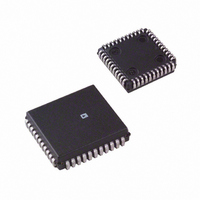
AD2S83IP-REEL Analog Devices Inc, AD2S83IP-REEL Datasheet - Page 13

AD2S83IP-REEL
Manufacturer Part Number
AD2S83IP-REEL
Description
IC R/D CONV TRACKING 44PLCC T/R
Manufacturer
Analog Devices Inc
Type
R/D Converterr
Datasheet
1.AD2S83IPZ-REEL.pdf
(19 pages)
Specifications of AD2S83IP-REEL
Rohs Status
RoHS non-compliant
Input Type
Parallel
Output Type
Digital
Interface
Parallel
Current - Supply
30mA
Mounting Type
Surface Mount
Package / Case
44-PLCC
During the VCO reset period the input continues to be inte-
grated. The reset period is constant at 40 ns.
The VCO rate is fixed for a given input current by the VCO
scaling factor:
The tracking rate in rps per µA of VCO input current can be
found by dividing the VCO scaling factor by the number of LSB
changes per rev (i.e., 4096 for 12-bit resolution).
The input resistor R6 determines the scaling between the con-
verter velocity signal voltage at the INTEGRATOR OUTPUT
pin and the VCO input current. Thus to achieve a 5 V output at
100 rps (6000 rpm) and 12-bit resolution the VCO input cur-
rent must be:
Thus, R6 would be set to: 5/(48.2 × 10
The velocity offset voltage depends on the VCO input resistor,
R6, and the VCO bias current and is given by
The temperature coefficient of this offset is given by
where the VCO bias current tempco is typically +0.22 nA/°C.
The maximum recommended rate for the VCO is 1.1 MHz
which sets the maximum possible tracking rate.
Since the minimum voltage swing available at the integrator
output is ± 8 V, this implies that the minimum value for R6 is
62 kΩ. As
Transfer Function
By selecting components using the method outlined in the sec-
tion “Component Selection,” the converter will have a critically
damped time response and maximum phase margin. The
Closed-Loop Transfer Function is given by:
where, s
and f
choice of external components).
The acceleration constant K
The normalized gain and phase diagrams are given in Figures 5
and 6.
Velocity Offset Tempco = R6 × (VCO bias current tempco)
BW
N
Velocity Offset Voltage = R6 × (VCO bias current)
is the closed-loop 3 dB bandwidth (selected by the
, the normalized frequency variable is given by:
θ
θ
OUT
IN
Max Current
Min Value R
(100 × 4096)/(8500) = 48.2 µA
=
( s
K
N
A
= 6 × ( f
+ 2.4)( s
= 8.5 kHz/µA
6
s
=
A
N
=
, is given approximately by
1 1 10
8 5 10
14 (1 + s
129 10
=
.
.
BW
×
2
×
N
π
2
×
8
)
+ 3.4 s
2
6
f
3
–6
BW
sec
–
s
N
=
6
) = 103.7 kΩ
129
)
=
–2
62
N
µ
+ 5.8)
k
A
Ω
–135
–180
–12
180
135
–45
–90
12
–3
–6
–9
90
45
9
6
3
0
0
0.0
0.0
0.04
0.04
0.1
0.1
FREQUENCY – f
FREQUENCY – f
0.2
0.2
BW
BW
0.4
0.4
AD2S83
1
1
2
2


