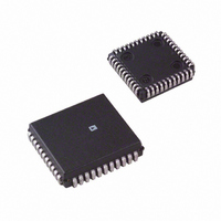
AD2S83IP-REEL Analog Devices Inc, AD2S83IP-REEL Datasheet - Page 14

AD2S83IP-REEL
Manufacturer Part Number
AD2S83IP-REEL
Description
IC R/D CONV TRACKING 44PLCC T/R
Manufacturer
Analog Devices Inc
Type
R/D Converterr
Datasheet
1.AD2S83IPZ-REEL.pdf
(19 pages)
Specifications of AD2S83IP-REEL
Rohs Status
RoHS non-compliant
Input Type
Parallel
Output Type
Digital
Interface
Parallel
Current - Supply
30mA
Mounting Type
Surface Mount
Package / Case
44-PLCC
AD2S83
The small signal step response is shown in Figure 7. The time
from the step to the first peak is t
the step until the converter is settled to 1 LSB. The times t
t
where R = resolution, i.e., 10, 12, 14 or 16.
The large signal step response (for steps greater than 5 degrees)
applies when the error voltage exceeds the linear range of the
converter.
Typically the converter will take three times longer to reach the
first peak for a 179 degrees step.
In response to a velocity step, the velocity output will exhibit
the same time response characteristics as outlined above for the
position output.
THE AD2S83 AS A SILICON TACHOGENERATOR
Position Control Using the AD2S83
The AD2S83 has been optimized for use as a feedback device
for velocity as well as position. A traditional position control
loop shown below compares a demand position with an actual
to derive a position error and hence a velocity demand.
Quality of control may be reduced if the load on a motor varies
dynamically. System reaction and compensation for a sudden
change in the loading depends on how rapidly the system can
update the velocity demand to the motor. This can cause rapid
acceleration of the motor until the loop updates with a new
velocity demand.
2
are given approximately by
POSITION
DEMAND
+
–
ACTUAL
POSITION
t
1
t
t
1
2
=
=
ELECTRONICS
t
2
f
f
CONTROL
POSITION
BW
1
BW
5
TERMS
1
, and the t
×
12
R
TIME
2
is the time from
FEEDBACK
SOURCE
MOTOR
1
and
The only effective way to compensate for dynamic loading
effects is to introduce a 2nd order term which will provide the
motor with an acceleration or deceleration demand signal (see
Figure 9).
Traditionally this would need to be implemented by using sepa-
rate position and speed feedback transducers, e.g., an encoder
or resolver and a dc tachogenerator. The AD2S83 can decode
the resolver to provide both velocity and position information.
DC Tachogenerator
The DC tachogenerator is a small permanent magnet dc
generator. The output is a dc voltage which is proportional to
the speed of the rotor and whose polarity is determined by the
direction of rotation. Physically they are similar to a resolver.
Velocity Error Derivation
The velocity error is the difference between the synthesized dc
velocity demand derived from the actual and demand positions
and the feedback from the tachogenerator or the AD2S83. The
velocity demand is usually derived via a DAC so apart from any
quantization noise it is clean. The velocity feedback, therefore,
needs to be as close to a pure dc level as possible. The errors
which determine the quality of the resultant acceleration demand
to the motor are explained below.
Linearity
Linearity is the maximum deviation from the ideal straight line
velocity characteristic. The line used is given by:
where
Linearity is generally a function of the input velocity to the
tachogenerator or resolver.
Reversion Error
Reversion or reversal error is an offset which is dependent on
the direction of rotation of the transducer; e.g., if 10 rps =
1.000 V dc, then –10 rps = 1.003 V dc with +0.3% reversion
error and FSO = ± 8 V dc.
Zero Velocity DC Offset
This is a residual dc offset present at zero input velocity. This
can be externally nulled.
v = velocity
m = gain scaling
x = dc voltage
c = zero velocity dc offset
POSITION
DEMAND
+
–
ACTUAL
POSITION
ELECTRONICS
POSITION
v = mx + c
CONTROL
TERMS
ELECTRONICS
VELOCITY
FEEDBACK
MOTOR
SOURCE


