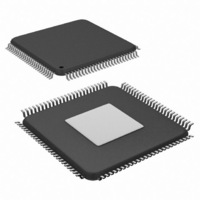
SCAN12100TYA/NOPB National Semiconductor, SCAN12100TYA/NOPB Datasheet - Page 19

SCAN12100TYA/NOPB
Manufacturer Part Number
SCAN12100TYA/NOPB
Description
IC SERIAL/DESERIAL CPRI 100-TQFP
Manufacturer
National Semiconductor
Series
SCANr
Datasheet
1.SCAN12100TYANOPB.pdf
(34 pages)
Specifications of SCAN12100TYA/NOPB
Function
Serializer/Deserializer
Data Rate
614.4Mbps
Input Type
LVTTL/LVCMOS
Output Type
LVTTL, LVCMOS
Number Of Inputs
10
Number Of Outputs
10
Voltage - Supply
1.8 V ~ 3.3 V
Operating Temperature
-40°C ~ 85°C
Mounting Type
Surface Mount
Package / Case
100-TQFP Exposed Pad, 100-eTQFP, 100-HTQFP, 100-VQFP
Lead Free Status / RoHS Status
Lead free / RoHS Compliant
Other names
SCAN12100TYA
Available stocks
Company
Part Number
Manufacturer
Quantity
Price
Company:
Part Number:
SCAN12100TYA/NOPB
Manufacturer:
Texas Instruments
Quantity:
10 000
SYSCLK AND RE REMOTE RADIO HEAD SYNCHRONIZATION
The SCAN12100 has independent transmit and receive PLLs
as well as an internal ~30.72 MHz oscillator for seamless RE
synchronization. Once the SCAN12100 locks to incoming
CPRI data, SysCLK becomes phase locked to the recovered
clock, automatically synchronizing the RE to the REC. This
phase lock transition occurs gracefully through analog circuit-
ry to allow downstream components to track the slight fre-
quency change from external clock to recovered clock. During
In multi-hop applications, using a jitter cleaner between
SysCLK and RefCLK is recommended to attenuate any ac-
cumulated jitter (< 5 MHz).
RECEIVER PLL LOCK DETECTION
The LOCKB pin indicates the lock status of the receive PLL.
When asserted high, the receive PLL is not locked to the in-
coming serial stream. When LOCKB is low, the receive PLL
is locked to the incoming serial stream. Line code violations
(LCVs) may or may not exist when the PLL is locked.
8B/10B DECODING AND CODE GROUP ALIGNMENT IN
8-BIT MODE
The 8b/10b encodes and decodes all valid Dx.y and Kx.y pat-
terns. These include K23.7, K27.7, K28.0, K28.1, K28.2,
K28.3, K28.4, K28.5, K28.6, K28.7, K29.7, and K30.7. The
receiver decodes invalid codes to K30.7. K-characters K28.1,
K28.5, and K28.7 each contain a comma bit sequence. When
comma alignment is enabled (CALIGN_EN = 1), the receiver
performs code group alignment when encountering a comma.
The CALIGN_EN pin allows the upper layer system to control
when alignment and realignment occurs.
COMMA DETECT (CDET) OPERATION
When a K character (K28.1, K28.5, or K28.7) is detected with
comma alignment enabled (CALIGN_EN = 1), the receiver
FIGURE 6. Radio Equipment (RE) Clock Syncronization
19
RE synchronization, TxCLK (and RxCLK if in read mode)
should be held static high or low to prevent FIFO over- or un-
der- flow
Unlike most SerDes, the SCAN12100 deserializer does not
depend on RefCLK . RefCLK can therefore be switched from
a local clock source (crystal oscillator) to the recovered clock
without the deserializer losing lock.
performs code group alignment, i.e. the receiver aligns ROUT
[9:0] data to the proper word boundary. When the comma is
detected, CDET remains high for one 8b/10b word output
(RXCLK period/2). When comma alignment is disabled
(CALIGN_EN = 0), commas are still detected and flagged at
pin CDET, but (re)alignment is not performed.
LOS DETECTION
LOS is set to HIGH during receiver power up, during hardware
reset (via RESETB pin), or during software (via RESETB
MDIO register) reset. LOS requires one K28.5 character and
valid line coding for 1 hyperframe in order to go from HIGH to
LOW. After initialization, the LOS is set on the condition
shown in the table below. When the deserializer loses lock,
LOS is not automatically set high since the deserializer con-
tinues to count LCV’s in order to determine LOS status ac-
cording to the CPRI standard.
20209530
www.national.com


