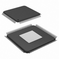
SCAN12100TYA/NOPB National Semiconductor, SCAN12100TYA/NOPB Datasheet - Page 3

SCAN12100TYA/NOPB
Manufacturer Part Number
SCAN12100TYA/NOPB
Description
IC SERIAL/DESERIAL CPRI 100-TQFP
Manufacturer
National Semiconductor
Series
SCANr
Datasheet
1.SCAN12100TYANOPB.pdf
(34 pages)
Specifications of SCAN12100TYA/NOPB
Function
Serializer/Deserializer
Data Rate
614.4Mbps
Input Type
LVTTL/LVCMOS
Output Type
LVTTL, LVCMOS
Number Of Inputs
10
Number Of Outputs
10
Voltage - Supply
1.8 V ~ 3.3 V
Operating Temperature
-40°C ~ 85°C
Mounting Type
Surface Mount
Package / Case
100-TQFP Exposed Pad, 100-eTQFP, 100-HTQFP, 100-VQFP
Lead Free Status / RoHS Status
Lead free / RoHS Compliant
Other names
SCAN12100TYA
Available stocks
Company
Part Number
Manufacturer
Quantity
Price
Company:
Part Number:
SCAN12100TYA/NOPB
Manufacturer:
Texas Instruments
Quantity:
10 000
HIGH SPEED DIFFERENTIAL I/O
PARALLEL DATA BUS
CLOCK SIGNALS
LINE STATUS
Pin Descriptions
Pin #
12
11
18
17
65
66
67
68
69
70
71
72
73
74
53
54
55
56
57
58
59
60
61
62
64
52
22
23
78
77
6
7
DOUTP
DOUTN
RINP
RINN
DIN [0]
DIN [1]
DIN [2]
DIN [3]
DIN [4]
DIN [5]
DIN [6]
DIN [7]
DIN [8]
DIN [9]
ROUT [0]
ROUT [1]
ROUT [2]
ROUT [3]
ROUT [4]
ROUT [5]
ROUT [6]
ROUT [7]
ROUT [8]
ROUT [9]
REFCLKP
REFCLKN
TXCLK
RXCLK
SYSCLKP
SYSCLKN
LOS
LOCKB
Pin Name
I/O, LVTTL or 1.8V
LVCMOS Internal
O, LVTTL or 1.8V
LVCMOS Internal
LVCMOS Internal
O, LVTTL or 1.8V
O, LVTTL or 1.8V
I, LVTTL or 1.8V
I, LVTTL or 1.8V
I, LVDS or
I/O, Type
pull down
pull down
pull down
LVCMOS
LVCMOS
LVCMOS
O, LVDS
LVPECL
O, CML
I, CML
Inverting and non-inverting high speed CML differential outputs of the serializer. On-
chip termination resistors connect from DO+ and DO− to an internal reference
Inverting and non-inverting high speed differential inputs of the deseralizer. On-chip
termination resistors connect from RI+ and RI− to an internal reference. On-chip
termination resistors are configured for AC-coupled applications.
Transmit data word.
In 10-bit mode, the 10-bit code-group at DIN [0–9] is serialized with the internal 8b/
10b encoder disabled. Bit 9 is the msb.
In 8-bit mode, DIN [0-7] is first converted into 10-bit code-group by the internal 8b/10b
encoder before it is serialized. Bit 7 is the msb. DIN [8] is used as K-code select pin
and DIN[9] should be tied Low. When DIN [8] is low, DIN [0-7] is mapped to the
corresponding 10-bit D-group. When DIN [8] is high, DIN [0-7] is mapped to the
corresponding 10-bit K-group.
The 8B/10B specification is defined in IEEE 802.3-2000 section 36.2.2
Deserialized receive data word.
In 10-bit mode, ROUT [0-9] is the deserialized received data word in 10-bit code group.
Bit 9 is the msb.
In 8-bit mode, ROUT [0-7] is the deserialized received data byte. Bit 7 is the msb.
ROUT [8] is the K-group indicator. A low at ROUT [8] indicates ROUT [0-7] belongs
to the D-group, while a high indicates it belongs to the K-group. ROUT [9] is the line
code violation (LCV) indicator. ROUT [9] is high for one ROUT cycle when a line code
violation occurs.
The 8B/10B specification is defined in IEEE 802.3-2000 section 36.2.2
Inverting and non-inverting differential serializer reference clock. A low jitter clock
source should be connected to REFCLKP & REFCLKN.
Transmit clock. TXCLK must be synchronous to REFCLK to avoid FIFO under/
overflow though it may differ in phase.
Write mode: RXCLK is recovered clock output pin.
Read mode: RXCLK is an input pin. ROUT [9:0] are latched out on RXCLK rising and
falling edges. RXCLK must be synchronous to the incoming serial data to avoid FIFO
over/underflow, though it may differ in phase. See RXCLKMODE pin description for
more details.
30.72 MHz output clock. (OPMODE must be low.)
Receiver CPRI loss of signal (LOS) status (8-bit mode only).
0 = signal detected (per CPRI standard)
1 = signal lost (per CPRI standard)
See “LOS Detection” under “Functional Description” for more details.
Receiver PLL lock status
0 = Receiver PLL locked
1 = Receiver PLL not locked
3
Description
www.national.com


