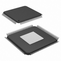
SCAN12100TYA/NOPB National Semiconductor, SCAN12100TYA/NOPB Datasheet - Page 20

SCAN12100TYA/NOPB
Manufacturer Part Number
SCAN12100TYA/NOPB
Description
IC SERIAL/DESERIAL CPRI 100-TQFP
Manufacturer
National Semiconductor
Series
SCANr
Datasheet
1.SCAN12100TYANOPB.pdf
(34 pages)
Specifications of SCAN12100TYA/NOPB
Function
Serializer/Deserializer
Data Rate
614.4Mbps
Input Type
LVTTL/LVCMOS
Output Type
LVTTL, LVCMOS
Number Of Inputs
10
Number Of Outputs
10
Voltage - Supply
1.8 V ~ 3.3 V
Operating Temperature
-40°C ~ 85°C
Mounting Type
Surface Mount
Package / Case
100-TQFP Exposed Pad, 100-eTQFP, 100-HTQFP, 100-VQFP
Lead Free Status / RoHS Status
Lead free / RoHS Compliant
Other names
SCAN12100TYA
Available stocks
Company
Part Number
Manufacturer
Quantity
Price
Company:
Part Number:
SCAN12100TYA/NOPB
Manufacturer:
Texas Instruments
Quantity:
10 000
www.national.com
The LOS mechanism affects the ROUT[9:0] and RXCLK out-
puts of the device under 8-bit mode. Upon power up, the
ROUT[9:0] and RXCLK pins will be static. Once LOS is low,
the device will send data on the ROUT[9:0] and RXCLK pins.
After LOS is high, the output will continue to send data for 2-3
hyperframes. If there are no line code violations during the
next hyperframe, the LOS signal goes low and resumes nor-
mal operation. If there are line code violations in the next 2-3
LOF (LOSS OF FRAME) DETECTION
LOF counter is provided through an LOF MDIO status register
per CPRI Specification. The LOF function is disabled in 10-
bit mode. Under 8-bit mode, LOF will prevent the SCAN12100
DCM scheme from activating. Delay calibration measurement
can only be performed when LOF is low.
TEST MODES
Loop Back Modes
The SCAN12100 supports multiple loop back modes for test-
ing device, link, and system operation. The line loop back
At-Speed Built-In Self-Test (BIST)
The SCAN12100 features at-speed built-in self-test (BIST) to
support at-speed testing during both manufacturing as well as
field diagnosis. Several test patterns are supported including
CJPAT lane 0 and PRWS 10.
BIST activation and status are accessed through the Serial
Control Interface (MDIO). Multiple registers are used for the
control, pattern selection, and customization of the at-speed
LOOP[1]
0 (BTS Mode)
0 (BTS Mode)
OPMODE
OPMODE
0
0
1
1
LOOP[0]
0
1
0
1
16 or more line code violations in a CPRI hyperframe
TABLE 14. Loopback Control Bit Settings
No LCVs occur within a CPRI hyperframe
TABLE 13. LOS Reset Conditions
TABLE 12. LOS Set Conditions
Normal mode—no loop back (enable software program mode)
Condition
Condition
20
Special line (remote) loop back
Line (remote) loop back mode
hyperframes, the outputs will be tri-stated and the device en-
ters a reset state.
The LOS function is disabled in 10-bit mode. The LOS de-
faults high in 10-bit mode.
The LOS signal is reset to low (signal detected) under the
following conditions:
mode enables the user to check the integrity of the serial data
transmission paths. The local loop back verifies operation of
the local board. When switching between normal mode and
loopback modes, the receiver must synchronize to the new
data stream.
Loopback mode can be controlled through the LOOP[1:0]
pins or via MDIO. Pulling LOOP[1:0] low enables MDIO con-
trol of loopback functions.
BIST function. The BIST test results are also reported in BIST
status MDIO registers. One-bit BIST_ DETECTED and
BIST_PASS status registers are provided to indicate BIST
start and pass/fail. A 10-bit counter is used to store the num-
ber of errors detected. See MDIO register list and program-
ming description for more information about at-speed BIST.
BIST is disabled in Line or Special Line loopback modes.
Local loop back mode
Loop Back Mode
LOS
LOS
1
0


