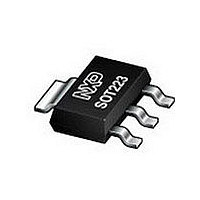
BSP250 NXP Semiconductors, BSP250 Datasheet - Page 3

BSP250
Manufacturer Part Number
BSP250
Description
Intermediate level P-channel enhancement mode Field-Effect Transistor (FET) in a plastic package using vertical D-MOS technology
Manufacturer
NXP Semiconductors
Type
Power MOSFETr
Datasheet
1.BSP250.pdf
(12 pages)
Specifications of BSP250
Number Of Elements
1
Polarity
P
Channel Mode
Enhancement
Drain-source On-res
0.25Ohm
Drain-source On-volt
30V
Gate-source Voltage (max)
±20V
Continuous Drain Current
3A
Power Dissipation
1.65W
Operating Temp Range
-65C to 150C
Operating Temperature Classification
Military
Mounting
Surface Mount
Pin Count
3 +Tab
Package Type
SOT-223
Lead Free Status / Rohs Status
Compliant
Available stocks
Company
Part Number
Manufacturer
Quantity
Price
Company:
Part Number:
BSP250
Manufacturer:
NXP
Quantity:
51 000
Part Number:
BSP250
Manufacturer:
NXP/恩智浦
Quantity:
20 000
Part Number:
BSP250,115
Manufacturer:
NEXPERIA/安世
Quantity:
20 000
Company:
Part Number:
BSP250115
Manufacturer:
NXP Semiconductors
Quantity:
109 000
Philips Semiconductors
LIMITING VALUES
In accordance with the Absolute Maximum Rating System (IEC 134).
Notes
1. Pulse width and duty cycle limited by maximum junction temperature.
2. Device mounted on an epoxy printed-circuit board, 40
1997 Jun 20
handbook, halfpage
V
V
I
I
P
T
T
Source-drain diode
I
I
SYMBOL
D
DM
S
SM
stg
j
DS
GSO
tot
P-channel enhancement mode
vertical D-MOS transistor
P tot
(W)
2.0
1.6
1.2
0.8
0.4
0
0
drain-source voltage (DC)
gate-source voltage (DC)
drain current (DC)
peak drain current
total power dissipation
storage temperature
operating junction temperature
source current (DC)
peak pulsed source current
Fig.2 Power derating curve.
50
100
PARAMETER
150
T amb ( C)
MLB885
200
3
40
open drain
T
note 1
T
T
T
note 1
s
s
amb
s
handbook, halfpage
= 100 C
Soldering point temperature T
(1) R
100 C
100 C
1.5 mm; mounting pad for drain lead minimum 6 cm
= 25 C; note 2
= 0.01.
CONDITIONS
(A)
10
10
I D
10
10
DSon
10
1
2
1
2
1
limitation.
P
t p
T
Fig.3 SOAR.
1
=
s
(1)
t p
T
t
= 100 C.
65
MIN.
DC
10
Product specification
5
1.65
+150
150
V DS (V)
3
1.5
30
20
12
6
MAX.
10 s
BSP250
1 ms
t p =
MLB835
10
V
V
A
A
W
W
A
A
2
C
C
UNIT
2
.


