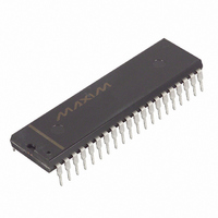
DS2180AN Maxim Integrated Products, DS2180AN Datasheet - Page 23

DS2180AN
Manufacturer Part Number
DS2180AN
Description
IC TRANSCEIVER T1 IND 40-DIP
Manufacturer
Maxim Integrated Products
Datasheet
1.DS2180A.pdf
(35 pages)
Specifications of DS2180AN
Function
Transceiver
Interface
T1
Number Of Circuits
1
Voltage - Supply
4.5 V ~ 5.5 V
Current - Supply
3mA
Operating Temperature
-40°C ~ 85°C
Mounting Type
Through Hole
Package / Case
40-DIP (0.600", 15.24mm)
Includes
Alarm Generation and Detection, B7 Stuffing Mode, B8ZS Mode, Error Detection and Counter, "Hardware" Mode, Transparent Mode
Lead Free Status / RoHS Status
Contains lead / RoHS non-compliant
Power (watts)
-
DS2180A
T1 OVERVIEW
Framing Standards
The DS2180A is compatible with the existing Bell System D4 framing standard described in ATT PUB
43801 and the new extended superframe format (ESF) as described in ATT C.B. #142. In this document,
D4 framing is referred to as 193S and ESF (also known as Fe) is referred to as 193E. Programmable
features of the DS2180A allow support of other framing standards which are derivatives of 193E and
193S. The salient differences between the 193S and 193E formats are the number of frames per
superframe and use of the F-bit position. In 193S, 12 frames make up a superframe, in 193E, 24. A frame
consists of 24 channels (timeslots) of 8-bit data preceded by an F-bit. Channel data is transmitted and
received MSB first.
F-Bits
The use of the F-bit position in 193S is split between the terminal framing pattern (know as F
-bits)
T
which pro-vides frame alignment information and the signaling framing pattern (known as F
-bits) which
S
provides multiframe alignment information. In 193E framing, the F-bit position is shared by the framing
pattern sequence (FPS) which provides frame and multiframe alignment information, a 4 kHz data link
known as FDL (Facility Data Link), and CRC (Cyclic Redundancy Check) bits. The FDL bits are used
for control and maintenance (inserted by the user at TLINK) and the CRC bits are an indicator of link
quality and may be monitored by the user to establish error performance.
Signaling
During frames 6 and 12 in 193S, A and B signaling information is inserted into the LSB of all channels
transmitted. In 193E, A and B data is inserted into frames 6 and 12 and C and D data is inserted into
frames 18 and 24. This allows a maximum of four signaling states to be transmitted per superframe in
193S and 16 states in 193E.
Alarms
The DS2180A supports all alarm pattern generation and detection required in typical Bell System
applications. These alarm modes are explained in ATT PUB 43801, ATT C.B. #142 and elsewhere in
this document.
23 of 35


