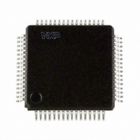
SC16C754BIBM,151 NXP Semiconductors, SC16C754BIBM,151 Datasheet - Page 14

SC16C754BIBM,151
Manufacturer Part Number
SC16C754BIBM,151
Description
IC UART QUAD W/FIFO 64-LQFP
Manufacturer
NXP Semiconductors
Datasheet
1.SC16C754BIB80557.pdf
(51 pages)
Specifications of SC16C754BIBM,151
Number Of Channels
4, QUART
Package / Case
64-LQFP
Fifo's
64 Byte
Voltage - Supply
2.5V, 3.3V, 5V
With Auto Flow Control
Yes
With False Start Bit Detection
Yes
With Modem Control
Yes
Mounting Type
Surface Mount
Data Rate
5 Mbps
Supply Voltage (max)
5.5 V
Supply Voltage (min)
2.25 V
Supply Current
6 mA
Maximum Operating Temperature
+ 85 C
Minimum Operating Temperature
- 40 C
Mounting Style
SMD/SMT
Operating Supply Voltage
2.5 V or 3.3 V or 5 V
Lead Free Status / RoHS Status
Lead free / RoHS Compliant
Lead Free Status / RoHS Status
Lead free / RoHS Compliant, Lead free / RoHS Compliant
Other names
568-3290
935279069151
SC16C754BIBM-S
935279069151
SC16C754BIBM-S
Available stocks
Company
Part Number
Manufacturer
Quantity
Price
Company:
Part Number:
SC16C754BIBM,151
Manufacturer:
NXP Semiconductors
Quantity:
10 000
NXP Semiconductors
SC16C754B_4
Product data sheet
6.4 Reset
UART1 begins transmission and sends 52 characters, at which point UART2 will generate
an interrupt to its processor to service the RX FIFO, but assumes the interrupt latency is
fairly long. UART1 will continue sending characters until a total of 60 characters have
been sent. At this time, UART2 will transmit a 0Fh to UART1, informing UART1 to halt
transmission. UART1 will likely send the 61
character. Now UART2 is serviced and the processor reads enough data out of the RX
FIFO that the level drops to 32. UART2 will now send a 0Dh to UART1, informing UART1
to resume transmission.
Table 4
Table 4.
Remark: Registers DLL, DLM, SPR, Xon1, Xon2, Xoff1, Xoff2 are not reset by the
top-level reset signal RESET, that is, they hold their initialization values during reset.
Table 5
Table 5.
Register
Interrupt enable register
Interrupt identification register
FIFO control register
Line control register
Modem control register
Line status register
Modem status register
Enhanced feature register
Receiver holding register
Transmitter holding register
Transmission control register
Trigger level register
Signal
TX
RTS
DTR
RXRDY
TXRDY
summarizes the state of register after reset.
summarizes the state of registers after reset.
Register reset functions
Signal RESET functions
5 V, 3.3 V and 2.5 V quad UART, 5 Mbit/s (max.) with 64-byte FIFOs
Rev. 04 — 6 October 2008
Reset control
RESET
RESET
RESET
RESET
RESET
RESET
RESET
RESET
RESET
RESET
RESET
RESET
Reset control
RESET
RESET
RESET
RESET
RESET
st
character while UART2 is sending the Xoff
Reset state
all bits cleared
bit 0 is set; all other bits cleared
all bits cleared
reset to 0001 1101 (1Dh)
all bits cleared
bit 5 and bit 6 set; all other bits cleared
bits 3:0 cleared; bits 7:4 input signals
all bits cleared
pointer logic cleared
pointer logic cleared
all bits cleared
all bits cleared
Reset state
HIGH
HIGH
HIGH
HIGH
LOW
SC16C754B
© NXP B.V. 2008. All rights reserved.
14 of 51


