SC28L198A1A,518 NXP Semiconductors, SC28L198A1A,518 Datasheet - Page 41

SC28L198A1A,518
Manufacturer Part Number
SC28L198A1A,518
Description
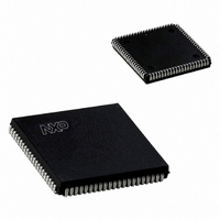
IC UART OCTAL SOT189-3
Manufacturer
NXP Semiconductors
Type
Octal UART for 3.3 V and 5 V supply voltager
Datasheet
1.SC28L198A1BE557.pdf
(57 pages)
Specifications of SC28L198A1A,518
Number Of Channels
8
Package / Case
84-LCC (J-Lead)
Features
False-start Bit Detection
Fifo's
16 Byte
Voltage - Supply
3.3V, 5V
With Auto Flow Control
Yes
With False Start Bit Detection
Yes
With Modem Control
Yes
With Cmos
Yes
Mounting Type
Surface Mount
Data Rate
0.4608 MBd
Supply Voltage (max)
5.5 V
Supply Voltage (min)
3 V
Supply Current
150 mA
Maximum Operating Temperature
+ 85 C
Minimum Operating Temperature
- 40 C
Mounting Style
SMD/SMT
Operating Supply Voltage
3.3 V or 5 V
Transmit Fifo
16Byte
Receive Fifo
16Byte
Transmitter And Receiver Fifo Counter
No
Operating Supply Voltage (typ)
3.3/5V
Package Type
PLCC
Operating Supply Voltage (max)
5.5V
Operating Supply Voltage (min)
3V
Mounting
Surface Mount
Operating Temperature (min)
-40C
Operating Temperature (max)
85C
Operating Temperature Classification
Industrial
Lead Free Status / RoHS Status
Lead free / RoHS Compliant
Lead Free Status / RoHS Status
Lead free / RoHS Compliant, Lead free / RoHS Compliant
Other names
935261323518
SC28L198A1A-T
SC28L198A1A-T
SC28L198A1A-T
SC28L198A1A-T
Philips Semiconductors
RESET CONDITIONS
Device Configuration after Hardware Reset or CRa
cmd=x1F
Cleared registers:
Clears Modes for:
2006 Aug 10
Octal UART for 3.3 V and 5 V supply voltage
Channel Status Registers (SR)
Channel Interrupt Status Registers (ISR)
Channel Interrupt Mask Registers (IMR)
Channel Interrupt Xon Status Register (XISR)
Interrupt Control Register (ICR)
Global Configuration Control Register (GCCR)
Hence the device enters the asynchronous bus cycling mode.
Current Interrupt Register (CIR)
BRG Timer Run Control Register (BRGTCR)
Watch-dog Timer Run Control Register (WDTRCR)
Channel Input/Output Port Configuration Registers (I/OPCR)
Hence all I/O pins have direction = Input after reset
BRG Counter/Timer Registers
Power down
41
Disables:
Halts:
Limitations:
Test modes
Input Port Changed bits
Gang write to Xon or Xoff
Xon/Xoff/Address detection
Receiver error status
Transmitters
Receivers
Interrupts, current and future
BRG Counters
Bus cycle in progress (hardware RESET only)
Minimum RESETN pin pulse width is 10 SClk cycles after Vcc
reaches operational range
The user must allow a minimum of 6 SClk cycles to elapse after
a reset (RESETN pin or CRa initiated) of the device terminates
before initiating a new bus cycle.
SC28L198
Product data sheet


