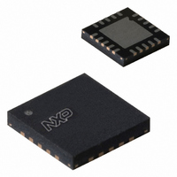
SA58637BS,118 NXP Semiconductors, SA58637BS,118 Datasheet - Page 4

SA58637BS,118
Manufacturer Part Number
SA58637BS,118
Description
IC AMP AUDIO 2.2W STER D 20HVQFN
Manufacturer
NXP Semiconductors
Type
Class Dr
Datasheet
1.SA58637BS118.pdf
(22 pages)
Specifications of SA58637BS,118
Output Type
2-Channel (Stereo)
Package / Case
20-VQFN Exposed Pad, 20-HVQFN, 20-SQFN, 20-DHVQFN
Max Output Power X Channels @ Load
2.2W x 2 @ 8 Ohm
Voltage - Supply
2.2 V ~ 18 V
Features
Mute, Short-Circuit and Thermal Protection, Standby
Mounting Type
Surface Mount
Product
Class-AB
Output Power
2.2 W
Available Set Gain
30 dB
Thd Plus Noise
0.15 %
Operating Supply Voltage
9 V
Supply Current
15 mA
Maximum Power Dissipation
2.2 W
Maximum Operating Temperature
+ 85 C
Mounting Style
SMD/SMT
Audio Load Resistance
8 Ohms
Input Bias Current (max)
500 nA
Input Signal Type
Differential
Minimum Operating Temperature
- 40 C
Output Signal Type
Differential, Single
Supply Type
Single
Supply Voltage (max)
18 V
Supply Voltage (min)
2.2 V
Operational Class
Class-AB
Audio Amplifier Output Configuration
2-Channel Stereo
Output Power (typ)
2.2x2@8OhmW
Audio Amplifier Function
Speaker
Total Harmonic Distortion
0.15@8Ohm@0.5W%
Single Supply Voltage (typ)
9V
Dual Supply Voltage (typ)
Not RequiredV
Power Supply Requirement
Single
Power Dissipation
2.2W
Rail/rail I/o Type
No
Power Supply Rejection Ratio
50dB
Single Supply Voltage (min)
2.2V
Single Supply Voltage (max)
18V
Dual Supply Voltage (min)
Not RequiredV
Dual Supply Voltage (max)
Not RequiredV
Operating Temp Range
-40C to 85C
Operating Temperature Classification
Industrial
Mounting
Surface Mount
Pin Count
20
Package Type
HVQFN EP
Lead Free Status / RoHS Status
Lead free / RoHS Compliant
Lead Free Status / RoHS Status
Lead free / RoHS Compliant, Lead free / RoHS Compliant
Other names
568-4356-2
935285742118
SA58637BS
SA58637BS-T
935285742118
SA58637BS
SA58637BS-T
NXP Semiconductors
7. Pinning information
SA58637_1
Product data sheet
7.1 Pinning
7.2 Pin description
Table 3.
[1]
Symbol
OUTL+
MODE
SVR
SELECT
n.c.
OUTR+
RGND
GND
V
OUTR
INR
INR+
INL+
INL
OUTL
V
LGND
Fig 2.
CCR
CCL
Pins 8, 9, 18 and 19 are connected to the lead frame and also to the substrate. They may be kept floating.
When connected to the ground plane, the PCB can be used as heatsink.
Pin configuration for HVQFN20
Pin description
Pin
1
2
3
4
5
6
7
8, 9, 18, 19
10
11
12
13
14
15
16
17
20
Rev. 01 — 25 February 2008
terminal 1
index area
SELECT
OUTR+
OUTL+
Description
positive loudspeaker terminal, left channel
operating mode select (standby, mute, operating)
half supply voltage, decoupling ripple rejection
BTL loudspeaker channel select (left, right, both channels)
not connected
positive loudspeaker terminal, right channel
ground, right channel
ground
supply voltage; right channel
negative loudspeaker terminal, right channel
negative input, right channel
positive input, right channel
positive input, left channel
negative input, left channel
negative output terminal, left channel
supply voltage, left channel
ground, left channel
MODE
SVR
n.c.
[1]
1
2
3
4
5
6
Transparent top view
SA58637BS
002aad578
16
15
14
13
12
11
2
OUTL
INL
INL+
INR+
INR
OUTR
2.2 W BTL audio amplifier
SA58637
© NXP B.V. 2008. All rights reserved.
4 of 22


