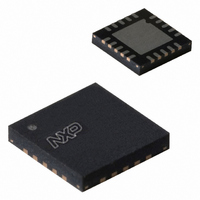
SA58637BS,118 NXP Semiconductors, SA58637BS,118 Datasheet - Page 6

SA58637BS,118
Manufacturer Part Number
SA58637BS,118
Description
IC AMP AUDIO 2.2W STER D 20HVQFN
Manufacturer
NXP Semiconductors
Type
Class Dr
Datasheet
1.SA58637BS118.pdf
(22 pages)
Specifications of SA58637BS,118
Output Type
2-Channel (Stereo)
Package / Case
20-VQFN Exposed Pad, 20-HVQFN, 20-SQFN, 20-DHVQFN
Max Output Power X Channels @ Load
2.2W x 2 @ 8 Ohm
Voltage - Supply
2.2 V ~ 18 V
Features
Mute, Short-Circuit and Thermal Protection, Standby
Mounting Type
Surface Mount
Product
Class-AB
Output Power
2.2 W
Available Set Gain
30 dB
Thd Plus Noise
0.15 %
Operating Supply Voltage
9 V
Supply Current
15 mA
Maximum Power Dissipation
2.2 W
Maximum Operating Temperature
+ 85 C
Mounting Style
SMD/SMT
Audio Load Resistance
8 Ohms
Input Bias Current (max)
500 nA
Input Signal Type
Differential
Minimum Operating Temperature
- 40 C
Output Signal Type
Differential, Single
Supply Type
Single
Supply Voltage (max)
18 V
Supply Voltage (min)
2.2 V
Operational Class
Class-AB
Audio Amplifier Output Configuration
2-Channel Stereo
Output Power (typ)
2.2x2@8OhmW
Audio Amplifier Function
Speaker
Total Harmonic Distortion
0.15@8Ohm@0.5W%
Single Supply Voltage (typ)
9V
Dual Supply Voltage (typ)
Not RequiredV
Power Supply Requirement
Single
Power Dissipation
2.2W
Rail/rail I/o Type
No
Power Supply Rejection Ratio
50dB
Single Supply Voltage (min)
2.2V
Single Supply Voltage (max)
18V
Dual Supply Voltage (min)
Not RequiredV
Dual Supply Voltage (max)
Not RequiredV
Operating Temp Range
-40C to 85C
Operating Temperature Classification
Industrial
Mounting
Surface Mount
Pin Count
20
Package Type
HVQFN EP
Lead Free Status / RoHS Status
Lead free / RoHS Compliant
Lead Free Status / RoHS Status
Lead free / RoHS Compliant, Lead free / RoHS Compliant
Other names
568-4356-2
935285742118
SA58637BS
SA58637BS-T
935285742118
SA58637BS
SA58637BS-T
NXP Semiconductors
9. Limiting values
10. Thermal characteristics
11. Static characteristics
Table 7.
V
SA58637_1
Product data sheet
Symbol
V
I
I
q
stb
CC
CC
= 6 V; T
Static characteristics
amb
Parameter
supply voltage
quiescent current
standby current
= 25 C; R
Table 4.
Voltage levels at control pins at V
[1]
[2]
[3]
[4]
[5]
Table 5.
In accordance with the Absolute Maximum Rating System (IEC 60134).
Table 6.
[1]
Control pin
MODE
HVCC
HVCC
HVCC
Symbol
V
V
I
T
T
V
P
Symbol
R
R
ORM
L
stg
amb
CC
I
CC(sc)
tot
th(j-a)
th(j-sp)
= 8 ; V
HIGH = V
n.c. = not connected or floating.
X = don’t care.
HVCC = 1.5 V < V
LOW = V
Thermal resistance is 22 K/W with DAP soldered to 64.5 mm
[4]
[4]
[4]
/LOW
/LOW
/LOW
MODE
Parameter
thermal resistance from
junction to ambient
thermal resistance from
junction to solder point
Parameter
supply voltage
input voltage
repetitive peak output current
storage temperature
ambient temperature
supply voltage (short circuit)
total power dissipation
Control pins MODE and SELECT versus status of output channels
Limiting values
Thermal characteristics
SELECT
SELECT
[5]
[5]
[5]
= 0 V; measured in test circuit
< 0.5 V.
> V
SELECT
HIGH
HVCC
LOW
SELECT
CC
Conditions
operating
R
V
Rev. 01 — 25 February 2008
MODE
L
[5]
[1]
=
[4]
0.5 V.
< V
/n.c.
CC
= V
[2]
CC
CC
1.5 V.
= 5 V; for other voltage levels see
Status of output channel
Left channel
mute/on
mute/on
standby
Conditions
in free air
with heat spreader
Conditions
operating
non-operating
operating
Figure
3; unless otherwise specified.
[1]
Min
2.2
-
-
2
(10 in
Right channel
standby
mute/on
mute/on
2
2
), 28.3 g (1 oz) copper heat spreader.
Min
-
-
-
2.2 W BTL audio amplifier
0.3
0.3
55
40
Figure 6
Typ
9
15
-
Max
+18
V
1
+150
+85
10
2.2
SA58637
© NXP B.V. 2008. All rights reserved.
and
[1]
CC
Max
18
22
10
Typical I
8
15
8
+ 0.3
Typ
80
22
3
Figure
…continued
q
7.
(mA)
Unit
K/W
K/W
K/W
Unit
V
V
A
V
W
Unit
V
mA
6 of 22
C
C
A


