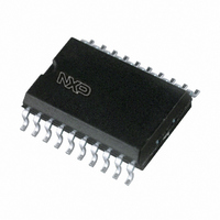
TDA8931T/N1,112 NXP Semiconductors, TDA8931T/N1,112 Datasheet - Page 6

TDA8931T/N1,112
Manufacturer Part Number
TDA8931T/N1,112
Description
IC AMP/COMPARATOR 22W D 20SOIC
Manufacturer
NXP Semiconductors
Type
Class Dr
Datasheet
1.TDA8931TN1112.pdf
(31 pages)
Specifications of TDA8931T/N1,112
Output Type
1-Channel (Mono)
Max Output Power X Channels @ Load
22W x 1 @ 4 Ohm
Voltage - Supply
12 V ~ 35 V, ±6 V ~ 17.5 V
Features
Depop, Short-Circuit and Thermal Protection
Mounting Type
Surface Mount
Package / Case
20-SOIC (7.5mm Width)
Lead Free Status / RoHS Status
Lead free / RoHS Compliant
Other names
568-3609-5
935276045112
TDA8931T
935276045112
TDA8931T
Philips Semiconductors
9397 750 13847
Preliminary data sheet
8.6.1 Overtemperature protection (OTP)
8.6.2 Overcurrent protection (OCP)
8.6.3 Overvoltage protection (OVP)
8.5 Half supply voltage capacitor charger (pin HVP)
8.6 Protections
Pin HVPI will be on its final level of 0.5V
into a plop-noise free start-up behavior.
When the device is in Standby mode, the SE capacitor C15 (see
until it reaches the half of the supply voltage. This current charges capacitor C15 within
0.5 seconds when a capacitor of 1000 F is used. When the voltage on pin HVP has
reached the level of 0.5V
When the device is in Operating mode, pin HVP is switched to floating to minimize
dissipation.
When the supply voltage drops, capacitor C15 is discharged and the device is switched off
to avoid plop noise.
Overtemperature, overcurrent, overvoltage and undervoltage sensors are included in the
TDA8931. When one of these sensors exceeds its threshold level the output power stage
is switched off and the output stage becomes floating. After 1.5 s the device will try to
restart. When the fault condition is removed the output stage is switched on.
Table 5:
[1]
If the junction temperature T
device will shut down immediately. The device will start switching again when the
temperature drops.
If the output current exceeds the maximum output current threshold level (e.g. when the
loudspeaker terminals are short-circuited it will be detected by the current protection) the
device will shut-down.
When the supply voltage applied to the TDA8931 exceeds the maximum supply voltage
threshold level the device will shut down. The supply voltage on which the device stops
operating is determined by two external resistors R1 and R2.
Protection
Symbol
OTP
OCP
OVP
UVP
ODP
Pin DIAG = LOW for minimal 1.5 s.
Overview protections
Condition
T
I
V
V
I
T
O
O
j
j
P
P
> 150 C
> 140 C
> I
> I
> V
< V
OCP
OCP
P(OVP)fix
P(UVP)
and
Rev. 01 — 14 January 2004
P
it releases pin ENABLE for external use.
Output
pin DIAG
LOW
LOW
j
exceeds the threshold level of approximately 150 C then the
[1]
Remark
self recovering when fault is removed
recovering by switching pin POWERUP: first to Sleep
mode and then to Standby mode
recovering by removing supply voltage
P
before the device starts switching. This results
© Koninklijke Philips Electronics N.V. 2005. All rights reserved.
Power comparator 1
Figure
TDA8931
5) will be charged
6 of 31
20 W


