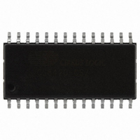
CS8420-CSZ Cirrus Logic Inc, CS8420-CSZ Datasheet - Page 23

CS8420-CSZ
Manufacturer Part Number
CS8420-CSZ
Description
IC SAMPLE RATE CONVERTER 28SOIC
Manufacturer
Cirrus Logic Inc
Type
Sample Rate Converterr
Specifications of CS8420-CSZ
Package / Case
28-SOIC
Applications
CD-R, DAT, DVD, MD, VTR
Mounting Type
Surface Mount
Operating Supply Voltage
5 V
Operating Temperature Range
- 10 C to + 70 C
Mounting Style
SMD/SMT
Resolution
17 bit to 24 bit
Control Interface
3 Wire, Serial
Supply Voltage Range
4.75V To 5.25V
Audio Ic Case Style
SOIC
No. Of Pins
28
Bandwidth
20kHz
Rohs Compliant
Yes
Audio Control Type
Volume
Dc
0841
Lead Free Status / RoHS Status
Lead free / RoHS Compliant
For Use With
598-1782 - EVALUATION BOARD FOR CS8420
Lead Free Status / Rohs Status
Lead free / RoHS Compliant
Other names
598-1125-5
Available stocks
Company
Part Number
Manufacturer
Quantity
Price
Company:
Part Number:
CS8420-CSZ
Manufacturer:
CIRRUS
Quantity:
319
Company:
Part Number:
CS8420-CSZ
Manufacturer:
CIRRUS
Quantity:
9 908
Part Number:
CS8420-CSZ
Manufacturer:
CIRRUS
Quantity:
20 000
Company:
Part Number:
CS8420-CSZ/D1
Manufacturer:
CIRRUS
Quantity:
378
Company:
Part Number:
CS8420-CSZR
Manufacturer:
NICHICON
Quantity:
4 200
automatically by the CS8420. However, certain
non-audio sources, such as AC3 or MPEG encod-
ers, may not adhere to this convention, and the bit
may not be properly set. The CS8420 AES3 receiv-
er can detect such non-audio data. This is accom-
plished by looking for a 96-bit sync code,
consisting of 0x0000, 0x0000, 0x0000, 0x0000,
0xF872, and 0x4E1F. When the sync code is de-
tected, an internal AUTODETECT signal will be
asserted. If no additional sync codes are detected
within the next 4096 frames, AUTODETECT will
be de-asserted until another sync code is detected.
The AUDIO bit in the Receiver Channel Status reg-
ister is the logical OR of AUTODETECT and the
received channel status bit 1. If non-audio data is
detected, the data is still processed exactly as if it
were normal audio. It is up to the user to mute the
outputs as required.
9.5
The AES3 transmitter encodes and transmits audio
and digital data according to the AES3, IEC60958
(S/PDIF), and EIAJ CP-1201 interface standards.
Audio and control data are multiplexed together
and bi-phase mark encoded. The resulting bit
stream is then driven directly, or through a trans-
former, to an output connector.
The transmitter is usually clocked from the output
side clock domain of the sample rate converter.
This clock may be derived from the clock input pin
OMCK, or from the incoming data. In data flows
with no SRC, and where OMCK is asynchronous to
the data source, an interrupt bit is provided that will
go high every time a data sample is dropped or re-
peated.
The channel status (C) and user channel (U) bits in
the transmitted data stream are taken from storage
areas within the CS8420. The user can manipulate
the contents of the internal storage with a micro-
controller. The CS8420 will also run in one of sev-
eral automatic modes. The Appendix: Channel Sta-
tus and User Data Buffer Management (page 72)
DS245PP2
AES3 Transmitter
provides detailed descriptions of each automatic
mode, and describes methods for accessing the
storage areas. The transmitted user data can option-
ally be input via the U pin, under the control of a
control port register bit. Figure 22 shows the timing
requirements for inputting U data via the U pin.
9.5.1
The TCBL pin may be an input or an output, and is
used to control or indicate the start of transmitted
channel status block boundaries.
In some applications, it may be necessary to control
the precise timing of the transmitted AES3 frame
boundaries. This may be achieved in 3 ways:
a) With TCBL configured as an input, when TCBL
transitions high for >3 OMCK clocks, it will cause
a frame start, and a new channel status block start.
b) If the AES3 output comes from the AES3 input,
while there is no SRC, setting TCBL as output will
cause AES3 output frame boundaries to align with
AES3 input frame boundaries.
c) If the AES3 output comes from the serial audio
input port while the port is in slave mode, and
TCBL is set to output, then the start of the A chan-
nel sub-frame will be aligned with the leading edge
of ILRCK.
9.5.2
The line drivers are low skew, low impedance, dif-
ferential outputs capable of driving cables directly.
Both drivers are set to ground during reset (RST =
low), when no AES3 transmit clock is provided,
and optionally under the control of a register bit.
The CS8420 also allows immediate mute of the
AES3 transmitter audio data via a control register
bit.
External components are used to terminate and iso-
late the external cable from the CS8420. These
components are detailed in the Appendix “External
Transmitted Frame and Channel
Status Boundary Timing
TXN and TXP Drivers
CS8420
23


