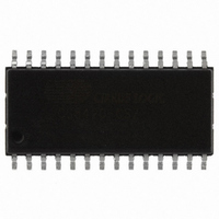
CS8420-CSZ Cirrus Logic Inc, CS8420-CSZ Datasheet - Page 37

CS8420-CSZ
Manufacturer Part Number
CS8420-CSZ
Description
IC SAMPLE RATE CONVERTER 28SOIC
Manufacturer
Cirrus Logic Inc
Type
Sample Rate Converterr
Specifications of CS8420-CSZ
Package / Case
28-SOIC
Applications
CD-R, DAT, DVD, MD, VTR
Mounting Type
Surface Mount
Operating Supply Voltage
5 V
Operating Temperature Range
- 10 C to + 70 C
Mounting Style
SMD/SMT
Resolution
17 bit to 24 bit
Control Interface
3 Wire, Serial
Supply Voltage Range
4.75V To 5.25V
Audio Ic Case Style
SOIC
No. Of Pins
28
Bandwidth
20kHz
Rohs Compliant
Yes
Audio Control Type
Volume
Dc
0841
Lead Free Status / RoHS Status
Lead free / RoHS Compliant
For Use With
598-1782 - EVALUATION BOARD FOR CS8420
Lead Free Status / Rohs Status
Lead free / RoHS Compliant
Other names
598-1125-5
Available stocks
Company
Part Number
Manufacturer
Quantity
Price
Company:
Part Number:
CS8420-CSZ
Manufacturer:
CIRRUS
Quantity:
319
Company:
Part Number:
CS8420-CSZ
Manufacturer:
CIRRUS
Quantity:
9 908
Part Number:
CS8420-CSZ
Manufacturer:
CIRRUS
Quantity:
20 000
Company:
Part Number:
CS8420-CSZ/D1
Manufacturer:
CIRRUS
Quantity:
378
Company:
Part Number:
CS8420-CSZR
Manufacturer:
NICHICON
Quantity:
4 200
11.9
VFIFO
REUNLOCK
DETU
EFTU
QCH
UOVW
11.10 Interrupt 1 Register Mask (9)
11.11 Interrupt Register 1 Mode Registers MSB & LSB(10,11)
DS245PP2
TSLIPM
TSLIP1
TSLIP0
7
0
7
7
Interrupt Register 2 Status (8) (Read Only)
For all bits in this register, a “1” means the associated interrupt condition has occurred at least once
since the register was last read. A ”0” means the associated interrupt condition has NOT occurred
since the last reading of the register. Reading the register resets all bits to 0, unless the interrupt mode
is set to level and the interrupt source is still true. Status bits that are masked off in the associated
mask register will always be “0” in this register. This register defaults to 00.
The bits of this register serve as a mask for the Interrupt 1 Register. If a mask bit is set to 1, the error
is considered unmasked, meaning that its occurrence will affect the INT pin and the status register. If
a mask bit is set to 0, the error is considered masked, meaning that its occurrence will not affect the
INT pin or the status register. The bit positions align with the corresponding bits in Interrupt Register
1. This register defaults to 00.
The two Interrupt Mode registers form a 2-bit code for each Interrupt Register 1 function. This code
determines whether the INT pin is set active on the arrival of the interrupt condition, on the removal
of the interrupt condition, or on the continuing occurrence of the interrupt condition. These registers
default to 00.
00 - Rising edge active
01 - Falling edge active
10 - Level active
11 - Reserved
OSLIPM
OSLIP1
OSLIP0
cur if the input sample rate slows too fast.
ing input or output sample rate.
in the U bit buffer management process (block mode only).
in the U bit buffer management process (block mode only).
in 588 AES3 frames after the interrupt occurs to avoid corruption of the data by the next block.
Varispeed FIFO overflow indicator. Occurs if the data buffer in the SRC overflows. This will oc-
Sample rate converter unlock indicator. This interrupt occurs if the SRC is still tracking a chang-
D to E U-buffer transfer interrupt. The source of this bit is true during the D to E buffer transfer
E to F U-buffer transfer interrupt. The source of this bit is true during the E to F buffer transfer
A new block of Q-subcode data is available for reading. The data must be completely read with-
U-bit FIFO Overwrite. This interrupt occurs on an overwrite in the U-bit FIFO.
6
6
6
0
VFIFO
SREM
SRE1
SRE0
5
5
5
REUNLOCK
OVRGLM
OVRGL1
OVRGL0
4
4
4
OVRGRM
OVRGR1
OVRGR0
DETU
3
3
3
DETCM
DETC1
DETC0
EFTU
2
2
2
EFTCM
EFTC1
EFTC0
QCH
1
1
1
CS8420
RERRM
RERR1
RERR0
UOVW
0
0
0
37


