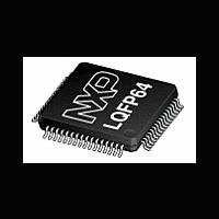
LPC2194 NXP Semiconductors, LPC2194 Datasheet - Page 12

LPC2194
Manufacturer Part Number
LPC2194
Description
The LPC2194 is based on a 16/32-bit ARM7TDMI-S CPU with real-time emulation andembedded trace support, together with 256 kB of embedded high-speed flash memory
Manufacturer
NXP Semiconductors
Datasheet
1.LPC2194.pdf
(41 pages)
Available stocks
Company
Part Number
Manufacturer
Quantity
Price
Part Number:
LPC2194FBD64
Manufacturer:
NXP/恩智浦
Quantity:
20 000
Company:
Part Number:
LPC2194HBD64
Manufacturer:
NXP
Quantity:
10 000
Company:
Part Number:
LPC2194HBD64,151
Manufacturer:
NXP Semiconductors
Quantity:
10 000
Company:
Part Number:
LPC2194HBD64/01
Manufacturer:
NXP
Quantity:
5 000
Company:
Part Number:
LPC2194HBD64/01,15
Manufacturer:
Maxim
Quantity:
60
Company:
Part Number:
LPC2194HBD64/01,15
Manufacturer:
NXP Semiconductors
Quantity:
10 000
Part Number:
LPC2194HBD64/01,15
Manufacturer:
NXP/恩智浦
Quantity:
20 000
Company:
Part Number:
LPC2194JBD64,151
Manufacturer:
NXP Semiconductors
Quantity:
10 000
NXP Semiconductors
LPC2194
Product data sheet
6.5.1 Interrupt sources
Vectored IRQs have the middle priority. Sixteen of the interrupt requests can be assigned
to this category. Any of the interrupt requests can be assigned to any of the 16 vectored
IRQ slots, among which slot 0 has the highest priority and slot 15 has the lowest.
Non-vectored IRQs have the lowest priority.
The VIC combines the requests from all the vectored and non-vectored IRQs to produce
the IRQ signal to the ARM processor. The IRQ service routine can start by reading a
register from the VIC and jumping there. If any of the vectored IRQs are requesting, the
VIC provides the address of the highest-priority requesting IRQs service routine,
otherwise it provides the address of a default routine that is shared by all the non-vectored
IRQs. The default routine can read another VIC register to see what IRQs are active.
Table 3
one interrupt line connected to the Vectored Interrupt Controller, but may have several
internal interrupt flags. Individual interrupt flags may also represent more than one
interrupt source.
Table 3.
Block
SPI1 and SSP
PLL
RTC
WDT
-
ARM Core
ARM Core
Timer 0
Timer 1
UART0
UART1
PWM0
I
SPI0
2
C-bus
lists the interrupt sources for each peripheral function. Each peripheral device has
Interrupt sources
[1]
All information provided in this document is subject to legal disclaimers.
Flag(s)
Watchdog Interrupt (WDINT)
Reserved for software interrupts only
EmbeddedICE, DbgCommRx
EmbeddedICE, DbgCommTx
Match 0 to 3 (MR0, MR1, MR2, MR3)
Capture 0 to 3 (CR0, CR1, CR2, CR3)
Match 0 to 3 (MR0, MR1, MR2, MR3)
Capture 0 to 3 (CR0, CR1, CR2, CR3)
Rx Line Status (RLS)
Transmit Holding Register empty (THRE)
Rx Data Available (RDA)
Character Time-out Indicator (CTI)
Rx Line Status (RLS)
Transmit Holding Register empty (THRE)
Rx Data Available (RDA)
Character Time-out Indicator (CTI)
Modem Status Interrupt (MSI)
Match 0 to 3 (MR0, MR1, MR2, MR3, MR4, MR5, MR6)
SI (state change)
SPIF, MODF
SPIF, MODF and TXRIS, RXRIS, RTRIS, RORRIS
PLL Lock (PLOCK)
RTCCIF (Counter Increment), RTCALF (Alarm)
Rev. 6 — 14 June 2011
Single-chip 16/32-bit microcontroller
LPC2194
© NXP B.V. 2011. All rights reserved.
VIC channel #
0
1
2
3
4
5
6
7
8
9
10
11
12
13
12 of 41


