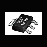
PHT8N06LT NXP Semiconductors, PHT8N06LT Datasheet - Page 2

PHT8N06LT
Manufacturer Part Number
PHT8N06LT
Description
Logic level N-channel enhancement mode Field-Effect Transistor (FET) in a plastic package using TrenchMOS technology
Manufacturer
NXP Semiconductors
Datasheet
1.PHT8N06LT.pdf
(9 pages)
Available stocks
Company
Part Number
Manufacturer
Quantity
Price
Company:
Part Number:
PHT8N06LT
Manufacturer:
NXP
Quantity:
60 000
Part Number:
PHT8N06LT
Manufacturer:
NXP/恩智浦
Quantity:
20 000
Company:
Part Number:
PHT8N06LTЈ¬135
Manufacturer:
NXP
Quantity:
36 000
Philips Semiconductors
THERMAL RESISTANCES
STATIC CHARACTERISTICS
T
DYNAMIC CHARACTERISTICS
T
REVERSE DIODE LIMITING VALUES AND CHARACTERISTICS
T
January 1998
TrenchMOS
Logic level FET
SYMBOL
R
R
j
SYMBOL PARAMETER
V
V
I
I
R
mb
SYMBOL PARAMETER
g
Q
Q
Q
C
C
C
t
t
t
t
j
SYMBOL PARAMETER
I
I
V
t
Q
= 25˚C unless otherwise specified
DSS
GSS
d on
r
d off
f
DR
DRM
rr
= -55 to 175˚C unless otherwise specified
V
fs
(BR)DSS
GS(TO)
SD
th j-sp
th j-amb
DS(ON)
iss
oss
rss
g(tot)
gs
gd
rr
= 25˚C unless otherwise specified
(BR)GSS
Drain-source breakdown
voltage
Gate threshold voltage
Zero gate voltage drain current
Gate source leakage current
Gate source breakdown voltage I
Drain-source on-state
resistance
Forward transconductance
Total gate charge
Gate-source charge
Gate-drain (Miller) charge
Input capacitance
Output capacitance
Feedback capacitance
Turn-on delay time
Turn-on rise time
Turn-off delay time
Turn-off fall time
Continuous reverse drain
current
Pulsed reverse drain current
Diode forward voltage
Reverse recovery time
Reverse recovery charge
PARAMETER
From junction to solder point
From junction to ambient
transistor
CONDITIONS
V
V
V
V
V
CONDITIONS
V
I
V
V
V
T
CONDITIONS
T
T
I
I
V
G
D
F
F
j
sp
sp
GS
DS
DS
GS
GS
DS
GS
DD
GS
GS
= 7 A; V
= 5 A; V
= 5 A; -dI
= 1 mA
= 25˚C
= 25˚C
= 25˚C
= 0 V; I
= V
= 55 V; V
= 5 V
= 5 V; I
= 25 V; I
= 0 V; V
= 30 V; I
= 5 V; R
= -10 V; V
CONDITIONS
Mounted on any PCB
Mounted on PCB of Fig.17
GS
; I
DD
GS
2
D
D
D
F
DS
/dt = 100 A/ s;
= 44 V; V
G
D
D
= 0 V
= 0.25 mA
= 1 mA
= 5 A
GS
= 10 ;
= 5 A; T
= 7 A;
R
= 25 V; f = 1 MHz
= 30 V
= 0 V;
GS
j
= 25˚C
T
T
T
T
= 5 V
T
T
j
j
j
j
j
j
= 150˚C
= 150˚C
= 150˚C
= 150˚C
= -55˚C
= -55˚C
TYP.
MIN.
MIN.
MIN.
12
1.0
0.6
-
55
50
10
4
-
-
-
-
-
-
-
-
-
-
-
-
-
-
-
-
-
-
-
-
-
-
TYP.
TYP.
TYP.
0.05
0.02
11.2
0.85
500
110
1.5
2.2
0.2
65
60
10
30
30
30
38
5
-
-
-
-
-
-
-
-
-
-
-
Product specification
MAX.
15
70
PHT8N06LT
MAX.
MAX.
MAX.
100
148
650
135
2.0
2.3
7.5
1.1
10
80
85
15
50
45
40
40
1
5
-
-
-
-
-
-
-
-
-
-
Rev 1.100
UNIT
K/W
K/W
UNIT
UNIT
UNIT
m
m
nC
nC
nC
pF
pF
pF
ns
ns
ns
ns
ns
V
V
V
V
V
V
S
A
A
V
C
A
A
A
A


