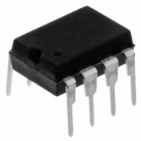
11LC160-I/P Microchip Technology, 11LC160-I/P Datasheet - Page 13

11LC160-I/P
Manufacturer Part Number
11LC160-I/P
Description
IC EEPROM 16KBIT 100KHZ 8DIP
Manufacturer
Microchip Technology
Datasheets
1.11LC010T-ITT.pdf
(44 pages)
2.11LC010T-ITT.pdf
(22 pages)
3.11LC010T-ITT.pdf
(6 pages)
4.11LC160T-ITT.pdf
(38 pages)
Specifications of 11LC160-I/P
Memory Size
16K (2K x 8)
Package / Case
8-DIP (0.300", 7.62mm)
Operating Temperature
-40°C ~ 85°C
Format - Memory
EEPROMs - Serial
Memory Type
EEPROM
Speed
100kHz
Interface
UNI/O™ (Single Wire)
Voltage - Supply
2.5 V ~ 5.5 V
Organization
2048 x 8
Interface Type
Serial
Maximum Clock Frequency
100 KHz
Supply Voltage (max)
5.5 V
Supply Voltage (min)
2.5 V
Maximum Operating Current
50 uA
Maximum Operating Temperature
+ 85 C
Mounting Style
Through Hole
Minimum Operating Temperature
- 40 C
Operating Supply Voltage
3.3 V, 5 V
Lead Free Status / RoHS Status
Lead free / RoHS Compliant
Lead Free Status / RoHS Status
Lead free / RoHS Compliant, Lead free / RoHS Compliant
7.0
In order to differentiate individual slave devices on the
bus, a device address byte is sent by the master
device following the start header. This is an 8-bit value
used to select a specific device attached to the bus.
The device address byte consists of a 4-bit family code
and a 4-bit device code. The device code may be
either fixed or programmable in order to provide the
ability to cascade multiple devices with identical family
codes on the same bus.
FIGURE 7-1:
7.1
The upper nibble (bits A
the family code. This code is a 4-bit value and speci-
fies in which family the device resides. The families
and codes are defined by Microchip and must be fol-
lowed in order to reduce the risk of address conflicts.
To obtain the proper code for a specific device, please
contact Microchip.
Certain codes have been reserved for special
functions and are listed in Table 7-1.
TABLE 7-1:
© 2009 Microchip Technology Inc.
‘0000’ Reserved for future use
‘0011’ Display Controllers
‘0100’ I/O Port Expanders
‘1000’ Frequency/Quadrature/PWM Encoders,
‘1001’ Temperature Sensors
‘1010’ EEPROMs
‘1011’ Encryption/Authentication Devices
‘1100’ DC/DC Converters
‘1101’ A/D Converters
‘1111’ 12-bit Addressable Devices
Code
A
7
Family Code
8-BIT DEVICE ADDRESSING
Family Code
Real-Time Clocks
A
6
DEVICE ADDRESS
A
5
RESERVED FAMILY CODES
A
8-BIT DEVICE ADDRESS
4
7
-A
Description
A
4
3
) of the device address is
Device Code
A
2
A
1
MAK
A
0
SAK
7.2
The lower nibble (bits A
the device code. This code is a 4-bit value and is used
to differentiate between multiple devices on the bus
within the same family. The device code is defined at
the device level and can be either fixed or customiz-
able. Such customizable bits can be implemented in
any manner, including via external input pins or
software configuration.
It is strongly recommended that as many customizable
device code bits as possible be included in order to
help avoid address conflicts.
Device Code
UNI/O
3
-A
0
) of the device address is
DS22076D-page 13
®
Bus


