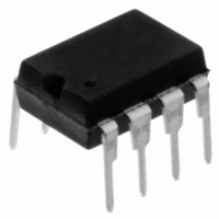
11LC160-I/P Microchip Technology, 11LC160-I/P Datasheet - Page 9

11LC160-I/P
Manufacturer Part Number
11LC160-I/P
Description
IC EEPROM 16KBIT 100KHZ 8DIP
Manufacturer
Microchip Technology
Datasheets
1.11LC010T-ITT.pdf
(44 pages)
2.11LC010T-ITT.pdf
(22 pages)
3.11LC010T-ITT.pdf
(6 pages)
4.11LC160T-ITT.pdf
(38 pages)
Specifications of 11LC160-I/P
Memory Size
16K (2K x 8)
Package / Case
8-DIP (0.300", 7.62mm)
Operating Temperature
-40°C ~ 85°C
Format - Memory
EEPROMs - Serial
Memory Type
EEPROM
Speed
100kHz
Interface
UNI/O™ (Single Wire)
Voltage - Supply
2.5 V ~ 5.5 V
Organization
2048 x 8
Interface Type
Serial
Maximum Clock Frequency
100 KHz
Supply Voltage (max)
5.5 V
Supply Voltage (min)
2.5 V
Maximum Operating Current
50 uA
Maximum Operating Temperature
+ 85 C
Mounting Style
Through Hole
Minimum Operating Temperature
- 40 C
Operating Supply Voltage
3.3 V, 5 V
Lead Free Status / RoHS Status
Lead free / RoHS Compliant
Lead Free Status / RoHS Status
Lead free / RoHS Compliant, Lead free / RoHS Compliant
3.0
Before communicating with a new device, a standby
pulse must be performed. This pulse signals to all
slave devices on the bus to enter Standby mode,
awaiting a new command to begin. The standby pulse
can also be used to prematurely terminate a
command.
The standby pulse consists of holding SCIO high for a
minimum of T
slave devices will be ready to receive a command.
Once a command is terminated satisfactorily (i.e., via
a NoMAK/SAK combination during the Acknowledge
sequence), performing a standby pulse is not required
to begin a new command as long as the device to be
selected is the same device selected during the previ-
ous command. In this case, a period of T
observed after the end of the command and before the
beginning of the start header. After T
header (including low pulse) can be transmitted in
order to begin the new command.
FIGURE 3-1:
Upon detection of the standby pulse, a slave device
will typically enter its lowest power state. The excep-
tion to this is when the slave device is executing an
internal process in the background. Examples include
an EEPROM performing a write cycle, or a tempera-
ture sensor carrying out a conversion.
If at any point during a command an error is detected
by the master, a standby pulse should be generated
and the command should be performed again.
© 2009 Microchip Technology Inc.
SCIO
SCIO
STANDBY PULSE
STBY
. After this has been performed, the
Standby Pulse
CONSECUTIVE COMMANDS EXAMPLE
0
Start Header
1
0
SS
1
SS
, the start
0
must be
0
Start Header
1
1
0
0
1
1
0
1
If a command is terminated in any manner other than a
NoMAK/SAK combination, or if an invalid number of
data bytes has been sent (as specified by the com-
mand’s definition), then this is considered an error
condition and the master must perform a standby
pulse before beginning a new command, regardless of
which device is to be selected.
An example of two consecutive commands is shown in
Figure 3-1. Note that the device address is the same
for both commands, indicating that the same device is
being selected both times.
1
0
Note: After a POR/BOR event occurs, a low-
0
Device Address
1
1
to-high transition on SCIO must be gen-
erated before proceeding with any com-
munication, including a standby pulse.
0
0
1
0
0
Device Address
0
1
0
UNI/O
0
0
0
0
0
DS22076D-page 9
®
Bus


