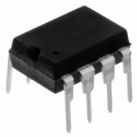
11LC160-I/P Microchip Technology, 11LC160-I/P Datasheet - Page 17

11LC160-I/P
Manufacturer Part Number
11LC160-I/P
Description
IC EEPROM 16KBIT 100KHZ 8DIP
Manufacturer
Microchip Technology
Datasheets
1.11LC010T-ITT.pdf
(44 pages)
2.11LC010T-ITT.pdf
(22 pages)
3.11LC010T-ITT.pdf
(6 pages)
4.11LC160T-ITT.pdf
(38 pages)
Specifications of 11LC160-I/P
Memory Size
16K (2K x 8)
Package / Case
8-DIP (0.300", 7.62mm)
Operating Temperature
-40°C ~ 85°C
Format - Memory
EEPROMs - Serial
Memory Type
EEPROM
Speed
100kHz
Interface
UNI/O™ (Single Wire)
Voltage - Supply
2.5 V ~ 5.5 V
Organization
2048 x 8
Interface Type
Serial
Maximum Clock Frequency
100 KHz
Supply Voltage (max)
5.5 V
Supply Voltage (min)
2.5 V
Maximum Operating Current
50 uA
Maximum Operating Temperature
+ 85 C
Mounting Style
Through Hole
Minimum Operating Temperature
- 40 C
Operating Supply Voltage
3.3 V, 5 V
Lead Free Status / RoHS Status
Lead free / RoHS Compliant
Lead Free Status / RoHS Status
Lead free / RoHS Compliant, Lead free / RoHS Compliant
11.0
11.1
Slave devices must feature a Idle mode during which
all serial data is ignored until a standby pulse occurs.
Idle mode will be entered, without generation of a
SAK, upon the following conditions:
An invalid start header cannot be detected, but will
indirectly also cause the device to enter Idle mode by
preventing the slave from synchronizing properly with
the master. If the slave is not synchronized with the
master, an edge transition will be missed, thus causing
the device to enter Idle mode.
11.2
Slave devices must feature a Standby mode during
which the device is waiting to begin a new command.
After observing the T
sition on SCIO will exit Standby and prepare the
device for reception of the start header.
Standby mode will be entered upon the following
conditions:
• A NoMAK followed by a SAK (i.e., valid termina-
• Reception of a standby pulse
Standby mode can be used to provide a low-power
mode of operation. In order to maximize power effi-
ciency, such a mode should be interrupted only at the
beginning of the low pulse of the start header.
FIGURE 11-1:
© 2009 Microchip Technology Inc.
• Invalid Device Address
• Invalid command byte
• Missed edge transition (except when entering
• Reception of a NoMAK before completing a
tion of a command)
Hold)
command sequence, except following a
device address
SCIO
DEVICE MODES
Device Idle
Device Standby
7 6 5 4
SS
Data Byte n
HOLD SEQUENCE
time period, a high-to-low tran-
3 2 1 0
Hold In Progress
11.3
Hold mode allows the master to suspend communica-
tion in order to perform other tasks, such as servicing
interrupts, etc. In order to initiate the Hold sequence,
the master must bring SCIO low at the beginning of
the next MAK bit period for a minimum time of T
and continue to keep it low while in hold.
To bring the slave out of hold, the master continues the
current operation, starting with an Acknowledge
sequence as described in Section 5.1 “Acknowledge
Sequence”, transmitting a MAK and checking for the
slave response. See Figure 11-1 for more details. The
Acknowledge sequence need not be in phase with
previously transmitted bits, thereby allowing the Hold
sequence to last for any length of time greater than
T
the hold sequence.
Note that if SCIO is held low for a full bit period (i.e., if
a middle edge does not occur) at any point other than
a MAK, the slave must consider this an error condition,
terminate the operation and enter Idle mode.
A Hold sequence must be terminated by issuing a
MAK. If a NoMAK is issued, there is no method for
detecting this, and the operation will be undefined.
Implementation of the Hold feature is optional. Without
it, a device may still conform to the UNI/O bus
specifications.
HLD
. The bit period must remain constant throughout
Device Hold
7 6 5 4
Data Byte n+1
UNI/O
3 2 1 0
DS22076D-page 17
®
Bus
HLD


