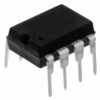
11LC160-I/P Microchip Technology, 11LC160-I/P Datasheet - Page 6

11LC160-I/P
Manufacturer Part Number
11LC160-I/P
Description
IC EEPROM 16KBIT 100KHZ 8DIP
Manufacturer
Microchip Technology
Datasheets
1.11LC010T-ITT.pdf
(44 pages)
2.11LC010T-ITT.pdf
(22 pages)
3.11LC010T-ITT.pdf
(6 pages)
4.11LC160T-ITT.pdf
(38 pages)
Specifications of 11LC160-I/P
Memory Size
16K (2K x 8)
Package / Case
8-DIP (0.300", 7.62mm)
Operating Temperature
-40°C ~ 85°C
Format - Memory
EEPROMs - Serial
Memory Type
EEPROM
Speed
100kHz
Interface
UNI/O™ (Single Wire)
Voltage - Supply
2.5 V ~ 5.5 V
Organization
2048 x 8
Interface Type
Serial
Maximum Clock Frequency
100 KHz
Supply Voltage (max)
5.5 V
Supply Voltage (min)
2.5 V
Maximum Operating Current
50 uA
Maximum Operating Temperature
+ 85 C
Mounting Style
Through Hole
Minimum Operating Temperature
- 40 C
Operating Supply Voltage
3.3 V, 5 V
Lead Free Status / RoHS Status
Lead free / RoHS Compliant
Lead Free Status / RoHS Status
Lead free / RoHS Compliant, Lead free / RoHS Compliant
UNI/O
1.2
1.2.1
SCIO is the only I/O signal required for the UNI/O bus.
Both the serial clock and data are embedded together
through Manchester encoding. In this encoding
method, each bit consists of a mandatory edge in the
middle of a bit period. The direction of this edge deter-
mines the value of the bit. A rising edge indicates a ‘
whereas a falling edge indicates a ‘
1.2.2
The master device determines the clock period, con-
trols bus access and initiates all operations. Only one
master is allowed in a system. Examples of master
devices include microcontrollers, ASICs and FPGAs.
1.2.3
A slave device acts as a peripheral on the bus. Slaves
do not initiate any operations; they merely respond to
operations begun by the master. Each slave must
have a unique device address with which the master
can select the device. Slave devices can operate as
both transmitter and receiver, but the mode is deter-
mined by the master in conjunction with the command
issued. Examples of slave devices include serial
EEPROMs, temperature sensors and A/D converters.
1.2.4
The transmitter is defined as the device with control of
the bus during transmission of a byte. For example,
while data is outputting from a slave to the master, the
slave is acting as the transmitter.
1.2.5
The receiver is defined as the device receiving the
current byte of data. For example, while a command is
being transmitted to a slave from the master, the slave
is acting as the receiver.
1.2.6
The bit period is defined as the amount of time
reserved for transmission of a single bit. This time
period is determined by the master. All slaves recover
this period through the start header by measuring the
amount of time needed to send the header.
For each bit, the Manchester-encoded bit edge must
occur at the middle of the bit period.
1.2.7
The high pulse used to place all slave devices into
Standby mode is called the standby pulse. It is
required at the beginning of a command when select-
ing a new device.
DS22076D-page 6
Definitions
SCIO
MASTER DEVICE
SLAVE DEVICE
TRANSMITTER
RECEIVER
BIT PERIOD
STANDBY PULSE
®
Bus
0
’.
1
’,
1.2.8
The start header is the combination of a short low
pulse followed by a header byte of the value
‘
for any given command.
After the header byte has been sent, an Acknowledge
sequence is performed. For this specific sequence
only, no slave responds during the normal SAK time.
1.2.9
Following the start header, the device address is sent.
This can consist of either one or two bytes, depending
on whether 8-bit or 12-bit device addressing is sup-
ported, respectively. The purpose of the device
address is to select a specific slave device on the bus.
For this reason, every slave device in a system must
have a unique device address. Otherwise, bus
conflicts will occur and operation will be undefined.
1.2.10
The family code is a 4-bit value included in the device
address and indicates the family in which the device
resides. Examples of device families include memory
devices, temperature sensors and A/D converters.
1.2.11
The device code is either a 4- or 8-bit value, depend-
ing on whether 8-bit or 12-bit device addressing is
supported, respectively. It is used to differentiate
devices with the same family code. Some devices may
support programmable device code bits, whereas on
others they may be fixed.
1.2.12
After each byte is transmitted, a 2-bit Acknowledge
sequence is performed. The first bit is for the MAK and
the second bit is for the SAK. The sequence is used to
indicate continuation or termination of an operation, as
well as to confirm reception of a byte.
1.2.13
The MAK bit occurs as the first bit of every Acknowl-
edge sequence. It is always sent by the master,
regardless of which device transmitted the preceding
byte. A MAK is sent as a ‘
Sending a MAK during an Acknowledge sequence
indicates that the current operation is to be continued.
This means that more data is to be sent by the device
acting as transmitter. A NoMAK indicates that the
current operation is to be terminated immediately
following the Acknowledge sequence.
01010101
START HEADER
DEVICE ADDRESS
FAMILY CODE
DEVICE CODE
ACKNOWLEDGE SEQUENCE
MAK/NOMAK
’. This is always the first byte transmitted
© 2009 Microchip Technology Inc.
1
’, and a NoMAK as a ‘
0
’.


