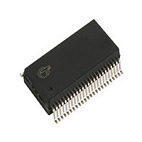
CY14B101LA-SP45XI Cypress Semiconductor Corp, CY14B101LA-SP45XI Datasheet - Page 10

CY14B101LA-SP45XI
Manufacturer Part Number
CY14B101LA-SP45XI
Description
IC NVSRAM 1MBIT 45NS 48SSOP
Manufacturer
Cypress Semiconductor Corp
Type
NVSRAMr
Datasheet
1.CY14B101LA-SP45XI.pdf
(26 pages)
Specifications of CY14B101LA-SP45XI
Format - Memory
RAM
Memory Type
NVSRAM (Non-Volatile SRAM)
Memory Size
1M (128K x 8)
Speed
45ns
Interface
Parallel
Voltage - Supply
2.7 V ~ 3.6 V
Operating Temperature
-40°C ~ 85°C
Package / Case
*
Word Size
8b
Organization
128Kx8
Density
1Mb
Interface Type
Parallel
Access Time (max)
45ns
Package Type
SSOP
Operating Temperature Classification
Industrial
Operating Supply Voltage (max)
3.6V
Operating Supply Voltage (min)
2.7V
Operating Temp Range
-40C to 85C
Pin Count
48
Mounting
Surface Mount
Supply Current
52mA
Memory Configuration
128K X 8
Access Time
45ns
Supply Voltage Range
2.7V To 3.6V
Memory Case Style
SSOP
No. Of Pins
48
Operating Temperature Range
-40°C To +85°C
Rohs Compliant
Yes
Lead Free Status / RoHS Status
Lead free / RoHS Compliant
Available stocks
Company
Part Number
Manufacturer
Quantity
Price
Company:
Part Number:
CY14B101LA-SP45XI
Manufacturer:
CY
Quantity:
35 792
Part Number:
CY14B101LA-SP45XI
Manufacturer:
CYPRESS/赛普拉斯
Quantity:
20 000
Data Retention and Endurance
Capacitance
Thermal Resistance
AC Test Conditions
Input pulse levels....................................................0 V to 3 V
Input rise and fall times (10% - 90%)............................ <3 ns
Input and output timing reference levels........................ 1.5 V
Note
Document #: 001-42879 Rev. *K
DATA
NV
C
C
Parameter
15. These parameters are guaranteed by design and are not tested.
Parameter
IN
OUT
C
Parameter
Θ
Θ
R
OUTPUT
JC
JA
[15]
[15]
3.0 V
Thermal resistance
(Junction to ambient)
Thermal resistance
(Junction to case)
Input capacitance (except BHE, BLE and HSB) T
Input capacitance (for BHE, BLE and HSB)
Output capacitance (except HSB)
Output capacitance (for HSB)
Data retention
Nonvolatile STORE operations
Description
30 pF
Description
577 Ω
Test conditions follow
standard test methods and
procedures for measuring
thermal impedance, in
accordance with
EIA/JESD51.
R1
Test Conditions
Description
789 Ω
Figure 5. AC Test Loads
R2
OUTPUT
V
54-TSOP II 48-SSOP 48-FBGA 44-TSOP II 32-SOIC Unit
A
CC
= 25 °C, f = 1 MHz,
10.13
36.4
= V
3.0 V
CC
(Typ)
Test Conditions
5 pF
37.47
24.71
38.58
11.71
577 Ω
R1
1,000
Min
20
41.74
11.90
CY14B101NA
CY14B101LA
for tristate specs
Max
789 Ω
7
8
7
8
R2
41.55
24.43
Page 10 of 26
Years
Unit
K
Unit
pF
pF
pF
pF
°C/W
°C/W
[+] Feedback


