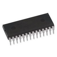
M27C512-90F6 STMicroelectronics, M27C512-90F6 Datasheet - Page 10

M27C512-90F6
Manufacturer Part Number
M27C512-90F6
Description
IC EPROM 512KBIT 90NS 28CDIP
Manufacturer
STMicroelectronics
Specifications of M27C512-90F6
Format - Memory
EPROMs
Memory Type
UV EPROM
Memory Size
512K (64K x 8)
Speed
90ns
Interface
Parallel
Voltage - Supply
4.5 V ~ 5.5 V
Operating Temperature
-40°C ~ 85°C
Package / Case
28-CDIP (0.600", 15.24mm) Window
Memory Configuration
64K X 8
Access Time
90ns
Supply Voltage Range
4.5V To 5V
Memory Case Style
DIP
No. Of Pins
28
Rohs Compliant
Yes
Lead Free Status / RoHS Status
Lead free / RoHS Compliant
Available stocks
Company
Part Number
Manufacturer
Quantity
Price
Company:
Part Number:
M27C512-90F6
Manufacturer:
ST
Quantity:
1 450
Company:
Part Number:
M27C512-90F6
Manufacturer:
ST
Quantity:
5 704
Company:
Part Number:
M27C512-90F6
Manufacturer:
ST
Quantity:
5 704
Part Number:
M27C512-90F6
Manufacturer:
ST
Quantity:
20 000
Company:
Part Number:
M27C512-90F6L
Manufacturer:
AD
Quantity:
196
Part Number:
M27C512-90F6L
Manufacturer:
ST
Quantity:
20 000
M27C512
DC AND AC PARAMETERS
This section summarizes the operating and mea-
surement conditions, and the DC and AC charac-
teristics of the device. The parameters in the DC
and AC Characteristic tables that follow are de-
rived from tests performed under the Measure-
Table 5. AC Measurement Conditions
Figure 7. Testing Input Output Waveform
Table 6. Capacitance
Note: 1. T
10/22
Input Rise and Fall Times
Input Pulse Voltages
Input and Output Timing Ref. Voltages
Symbol
High Speed
Standard
C
C
2.4V
0.4V
2. Sampled only, not 100% tested.
OUT
IN
3V
0V
A
= 25°C, f = 1MHz
Input Capacitance
Output Capacitance
Parameter
1.5V
2.0V
0.8V
AI01822
High Speed
0 to 3V
Test Condition
1.5V
ment Conditions summarized in the relevant
tables. Designers should check that the operating
conditions in their circuit match the measurement
conditions when relying on the quoted parame-
ters.
Figure 8. AC Testing Load Circuit
10ns
V
V
OUT
C L = 30pF for High Speed
C L = 100pF for Standard
C L includes JIG capacitance
IN
DEVICE
UNDER
TEST
= 0V
= 0V
(1,2)
1.3V
Min
1N914
3.3k
0.4V to 2.4V
0.8V and 2V
C L
Standard
20ns
Max
12
6
OUT
AI01823B
Unit
pF
pF


