DS2431X-S+ Maxim Integrated Products, DS2431X-S+ Datasheet - Page 6
DS2431X-S+
Manufacturer Part Number
DS2431X-S+
Description
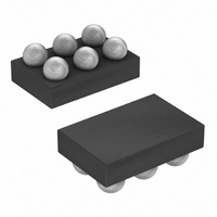
IC EEPROM 1KBIT 6UCSP
Manufacturer
Maxim Integrated Products
Datasheet
1.DS2431X-S.pdf
(26 pages)
Specifications of DS2431X-S+
Format - Memory
EEPROMs - Serial
Memory Type
EEPROM
Memory Size
1K (256 x 4)
Interface
1-Wire Serial
Operating Temperature
-40°C ~ 85°C
Package / Case
6-UCSP®
Lead Free Status / RoHS Status
Lead free / RoHS Compliant
Voltage - Supply
-
Speed
-


1024-Bit, 1-Wire EEPROM
The hierarchical structure of the 1-Wire protocol is
shown in Figure 2. The bus master must first provide
one of the seven ROM function commands: Read ROM,
Match ROM, Search ROM, Skip ROM, Resume,
Overdrive-Skip ROM, or Overdrive-Match ROM. Upon
completion of an Overdrive-Skip ROM or Overdrive-
Match ROM command byte executed at standard
speed, the device enters overdrive mode where all
subsequent communication occurs at a higher speed.
The protocol required for these ROM function com-
mands is described in Figure 9. After a ROM function
command is successfully executed, the memory func-
tions become accessible and the master can provide
any one of the four memory function commands. The
protocol for these memory function commands is
described in Figure 7. All data is read and written
least significant bit first.
Figure 2. Hierarchical Structure for 1-Wire Protocol
Figure 3. 64-Bit Lasered ROM
iButton is a registered trademark of Maxim Integrated Products, Inc.
6
_______________________________________________________________________________________
MSB
MSB
CRC CODE
8-BIT
1-Wire ROM FUNCTION COMMANDS
MEMORY FUNCTION COMMANDS
LSB
DS2431 COMMAND LEVEL:
DS2431-SPECIFIC
MSB
(SEE FIGURE 9)
(SEE FIGURE 7)
48-BIT SERIAL NUMBER
AVAILABLE COMMANDS:
READ ROM
MATCH ROM
SEARCH ROM
SKIP ROM
RESUME
OVERDRIVE-SKIP ROM
OVERDRIVE-MATCH ROM
WRITE SCRATCHPAD
READ SCRATCHPAD
COPY SCRATCHPAD
READ MEMORY
Each DS2431 contains a unique ROM code that is 64
bits long. The first 8 bits are a 1-Wire family code. The
next 48 bits are a unique serial number. The last 8 bits
are a cyclic redundancy check (CRC) of the first 56 bits.
See Figure 3 for details. The 1-Wire CRC is generated
using a polynomial generator consisting of a shift regis-
ter and XOR gates as shown in Figure 4. The polynomial
is X
1-Wire CRC is available in Application Note 27:
Understanding and Using Cyclic Redundancy Checks
with Maxim iButton
The shift register bits are initialized to 0. Then, starting
with the least significant bit of the family code, one bit
at a time is shifted in. After the 8th bit of the family code
has been entered, the serial number is entered. After
the last bit of the serial number has been entered, the
shift register contains the CRC value. Shifting in the 8
bits of the CRC returns the shift register to all 0s.
8
+ X
5
+ X
DATA FIELD AFFECTED:
64-BIT REG. #, RC-FLAG
64-BIT REG. #, RC-FLAG
64-BIT REG. #, RC-FLAG
RC-FLAG
RC-FLAG
RC-FLAG, OD-FLAG
64-BIT REG. #, RC-FLAG, OD-FLAG
64-BIT SCRATCHPAD, FLAGS
64-BIT SCRATCHPAD
DATA MEMORY, REGISTER PAGE
DATA MEMORY, REGISTER PAGE
4
+ 1. Additional information about the
®
Products .
LSB
MSB
64-Bit Lasered ROM
8-BIT FAMILY CODE
(2Dh)
LSB
LSB
Related parts for DS2431X-S+
Image
Part Number
Description
Manufacturer
Datasheet
Request
R

Part Number:
Description:
T2 CSP RDL/I°/1024-Bit 1-Wire EEPROM
Manufacturer:
Maxim Integrated Products
Part Number:
Description:
IC EEPROM 1KBIT 6UCSP
Manufacturer:
Maxim Integrated Products
Datasheet:
Part Number:
Description:
IC EEPROM 1KBIT TO92-3
Manufacturer:
Maxim Integrated Products
Datasheet:

Part Number:
Description:
IC EEPROM 1KBIT TO92-3
Manufacturer:
Maxim Integrated Products
Datasheet:
Part Number:
Description:
EEPROM
Manufacturer:
Maxim Integrated Products
Datasheet:

Part Number:
Description:
Ds2431 1024-bit 1-wire Eeprom
Manufacturer:
Maxim Integrated Products, Inc.
Datasheet:
Part Number:
Description:
power light source Luxeon Flood
Manufacturer:
LUMILEDS [Lumileds Lighting Company]
Datasheet:
Part Number:
Description:
MAX7528KCWPMaxim Integrated Products [CMOS Dual 8-Bit Buffered Multiplying DACs]
Manufacturer:
Maxim Integrated Products
Datasheet:
Part Number:
Description:
Single +5V, fully integrated, 1.25Gbps laser diode driver.
Manufacturer:
Maxim Integrated Products
Datasheet:
Part Number:
Description:
Single +5V, fully integrated, 155Mbps laser diode driver.
Manufacturer:
Maxim Integrated Products
Datasheet:
Part Number:
Description:
VRD11/VRD10, K8 Rev F 2/3/4-Phase PWM Controllers with Integrated Dual MOSFET Drivers
Manufacturer:
Maxim Integrated Products
Datasheet:
Part Number:
Description:
Highly Integrated Level 2 SMBus Battery Chargers
Manufacturer:
Maxim Integrated Products
Datasheet:
Part Number:
Description:
Current Monitor and Accumulator with Integrated Sense Resistor; ; Temperature Range: -40°C to +85°C
Manufacturer:
Maxim Integrated Products
Part Number:
Description:
TSSOP 14/A°/RS-485 Transceivers with Integrated 100O/120O Termination Resis
Manufacturer:
Maxim Integrated Products
Part Number:
Description:
TSSOP 14/A°/RS-485 Transceivers with Integrated 100O/120O Termination Resis
Manufacturer:
Maxim Integrated Products