EPC1213LC20 Altera, EPC1213LC20 Datasheet - Page 41
EPC1213LC20
Manufacturer Part Number
EPC1213LC20
Description
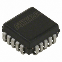
IC CONFIG DEVICE 212KBIT 20-PLCC
Manufacturer
Altera
Series
EPCr
Datasheet
1.EPC4QI100N.pdf
(116 pages)
Specifications of EPC1213LC20
Programmable Type
OTP
Memory Size
212kb
Voltage - Supply
4.75 V ~ 5.25 V
Operating Temperature
0°C ~ 70°C
Package / Case
20-PLCC
For Use With
PLMJ1213 - PROGRAMMER ADAPTER 20 PIN J-LEAD
Lead Free Status / RoHS Status
Contains lead / RoHS non-compliant
Other names
544-2188-5
Available stocks
Company
Part Number
Manufacturer
Quantity
Price
Company:

Part Number:
EPC1213LC20
Manufacturer:
AT
Quantity:
23
Company:
Part Number:
EPC1213LC20
Manufacturer:
ALTERA
Quantity:
5 510
Company:
Part Number:
EPC1213LC20
Manufacturer:
TI
Quantity:
5 510
Part Number:
EPC1213LC20
Manufacturer:
ALTERA/阿尔特拉
Quantity:
20 000


Chapter 2: Altera Enhanced Configuration Devices
Dynamic Configuration (Page Mode) Implementation Overview
Dynamic Configuration (Page Mode) Implementation Overview
© December 2009 Altera Corporation
1
Pages in enhanced configuration devices allow you to organize and store various
configurations for entire systems that use one or more Altera PLDs. This dynamic
configuration (or page mode) feature allows systems to dynamically reconfigure their
PLDs with different configuration files.
You can use different pages to store configuration files that support different
standards (for example, I/O standards, memory). Alternatively, the different pages
can place the system in different modes. For instance, page 0 could contain a
configuration .sof for the PLD that only processes data packets; page 1 could contain a
configuration file for the same PLD that processes data and voice packets.
With the ability to dynamically switch pages, you can also configure Altera devices
with various revisions for debugging without having to reprogram the configuration
device. For example, you can configure a device that is on “stand-by” to perform
another function and then reconfigure it back with the original configuration file.
A page is a section of the flash memory space that contains configuration data for all
PLDs in the system. One page stores one system configuration regardless of the
number of PLDs in the system. The size of each page is dynamic and can change each
time the enhanced configuration device is reprogrammed. Enhanced configuration
devices support a maximum of eight pages of configuration data, or eight system
configurations. The number of pages is also limited to the density of the configuration
device.
The number of pages required in a system is not dependent on the number of PLDs in
the system, but depends on the number of unique system configurations.
External page mode input pins PGM[2..0]determine which page to use during PLD
configuration, and page pointers determine the data location. Each page pointer
consists of a starting address register and a length count register. The word-
addressable starting address register (23 bits) is used to determine where the page
begins in the flash memory. The count register (25 bits) determines the length of the
page counted in nibbles (group of 4 bits equaling half of a byte).
block diagram of the option-bit space and its address locations.
Figure 2–4. Option-Bit Memory Map
For example, a page for the EPC16 configuration device must start between word
addresses 0x08020h and 0xFFFFFh and cannot overlap with other pages. Refer to
Figure 2–5
for an EPC16 page mode example using three pages.
0801Fh
08009h
08008h
24
8
15
24
8
15
24
8
15
CNT7
CNT1
CNT0
CNT1
ADDR1
ADDR0
ADDR7
CNT7
CNT0
0
0
0
22
22
22
Configuration Handbook (Complete Two-Volume Set)
ADDR0
ADDR7
ADDR1
16
16
16
9
0
9
0
9
0
Figure 2–4
shows a
2–5
Related parts for EPC1213LC20
Image
Part Number
Description
Manufacturer
Datasheet
Request
R

Part Number:
Description:
CUSTOMER ADVISORY EPC1064 and EPC1213 Transition Schedule Update
Manufacturer:
Altera Corporation
Part Number:
Description:
Configuration EPROMs For Flex Devices
Manufacturer:
Altera Corporation
Datasheet:

Part Number:
Description:
CYCLONE II STARTER KIT EP2C20N
Manufacturer:
Altera
Datasheet:

Part Number:
Description:
CPLD, EP610 Family, ECMOS Process, 300 Gates, 16 Macro Cells, 16 Reg., 16 User I/Os, 5V Supply, 35 Speed Grade, 24DIP
Manufacturer:
Altera Corporation
Datasheet:
Part Number:
Description:
CPLD, EP610 Family, ECMOS Process, 300 Gates, 16 Macro Cells, 16 Reg., 16 User I/Os, 5V Supply, 15 Speed Grade, 24DIP
Manufacturer:
Altera Corporation
Datasheet:
Part Number:
Description:
Manufacturer:
Altera Corporation
Datasheet:
Part Number:
Description:
CPLD, EP610 Family, ECMOS Process, 300 Gates, 16 Macro Cells, 16 Reg., 16 User I/Os, 5V Supply, 30 Speed Grade, 24DIP
Manufacturer:
Altera Corporation
Datasheet:
Part Number:
Description:
High-performance, low-power erasable programmable logic devices with 8 macrocells, 10ns
Manufacturer:
Altera Corporation
Datasheet:
Part Number:
Description:
High-performance, low-power erasable programmable logic devices with 8 macrocells, 7ns
Manufacturer:
Altera Corporation
Datasheet:
Part Number:
Description:
Classic EPLD
Manufacturer:
Altera Corporation
Datasheet:
Part Number:
Description:
High-performance, low-power erasable programmable logic devices with 8 macrocells, 10ns
Manufacturer:
Altera Corporation
Datasheet:
Part Number:
Description:
Manufacturer:
Altera Corporation
Datasheet:
Part Number:
Description:
Manufacturer:
Altera Corporation
Datasheet: