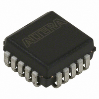
EPC1213LC20 Altera, EPC1213LC20 Datasheet - Page 47

EPC1213LC20
Manufacturer Part Number
EPC1213LC20
Description
IC CONFIG DEVICE 212KBIT 20-PLCC
Manufacturer
Altera
Series
EPCr
Datasheet
1.EPC4QI100N.pdf
(116 pages)
Specifications of EPC1213LC20
Programmable Type
OTP
Memory Size
212kb
Voltage - Supply
4.75 V ~ 5.25 V
Operating Temperature
0°C ~ 70°C
Package / Case
20-PLCC
For Use With
PLMJ1213 - PROGRAMMER ADAPTER 20 PIN J-LEAD
Lead Free Status / RoHS Status
Contains lead / RoHS non-compliant
Other names
544-2188-5
Available stocks
Company
Part Number
Manufacturer
Quantity
Price
Company:
Part Number:
EPC1213LC20
Manufacturer:
AT
Quantity:
23
Company:
Part Number:
EPC1213LC20
Manufacturer:
ALTERA
Quantity:
5 510
Company:
Part Number:
EPC1213LC20
Manufacturer:
TI
Quantity:
5 510
Part Number:
EPC1213LC20
Manufacturer:
ALTERA/阿尔特拉
Quantity:
20 000
Chapter 2: Altera Enhanced Configuration Devices
External Flash Memory Interface
Interface Availability and Connections
Quartus II Software Support
© December 2009 Altera Corporation
f
1
1
Flash memory ports are shared between the internal controller and the external
device. A processor or PLD can use the external flash interface to access flash memory
only when the controller is not using the interface. Therefore, the internal controller is
the primary master of the bus, while the external device is the secondary master.
Flash memory ports (address, data, and control) are internally connected to the
controller device. Additionally, these ports are connected to pins on the package
providing the external interface. During in-system programming of the enhanced
configuration device as well as configuration of the PLDs, the controller uses the
internal interface to flash memory, rendering the external interface unavailable.
External devices should tri-state all connections (address, data, and control) for the
entire duration of in-system programming and configuration to prevent contention.
On completion of in-system programming and configuration, the internal controller
tri-states its interface to the flash memory and enables weak internal pull-up resistors
on address and control lines as well as bus-hold circuits on the data lines. The internal
flash interface is now disabled and the external flash interface is available.
If you do not use the external flash interface feature, most flash-related pins must be
left unconnected on the board to avoid contention. There are a few exceptions to this
guideline outlined in the data sheet and pin-out tables.
For detailed schematics, refer to the
EPC16) Data
You can use the Convert Programming Files window to generate flash memory
programming files. You can program flash memory in-system using JTAG or through
the external flash interface. Select the .pof when programming the flash memory
in-system. You can also convert this .pof to a Jam
language (STAPL) file (.jam) or Jam Byte-Code file (.jbc) for in-system programming.
When programming the flash memory through the external flash interface, you can
create a .hexout from this window.
The .hexout used for programming enhanced configuration devices is different from
the .hexout configuration file generated for SRAM PLDs.
Along with PLD configuration files, you can program processor boot and application
code into flash memory through the Convert Programming Files window. You can
add a .hex file containing boot code to the Bottom Boot Data section of the window.
Similarly, you can add a .hex file containing application code to the Main Block Data
section. You can store these files in the flash memory using relative or absolute
addressing. For selecting the type of addressing, highlight the Bottom Boot Data or
Main Block Data section and click Properties (Convert Programming Files window).
Relative addressing mode allows the Quartus II software to pick the location of the
file in memory. For example, the Quartus II software always stores boot code starting
at address location 0x000000. This data increases to higher addresses.
Sheet.
Enhanced Configuration Devices (EPC4, EPC8, and
Configuration Handbook (Complete Two-Volume Set)
™
standard test and programming
2–11


