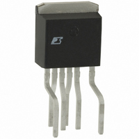
PKS606FN Power Integrations, PKS606FN Datasheet - Page 6

PKS606FN
Manufacturer Part Number
PKS606FN
Description
IC OFFLINE SWIT OTP OCP HV TO262
Manufacturer
Power Integrations
Series
PeakSwitch®r
Specifications of PKS606FN
Mfg Application Notes
PeakSwitch Design Guide AppNote
Output Isolation
Isolated
Frequency Range
250 ~ 304kHz
Voltage - Output
700V
Power (watts)
117W
Operating Temperature
-40°C ~ 150°C
Package / Case
TO-262-7 (Formed Leads), 5 Leads
Output Voltage
12 V
Input / Supply Voltage (max)
265 VAC
Input / Supply Voltage (min)
85 VAC
Duty Cycle (max)
65 %
Switching Frequency
47 KHz
Supply Current
25 uA
Operating Temperature Range
- 40 C to + 150 C
Mounting Style
Through Hole
For Use With
596-1198 - KIT REF DESIGN 36-72W MOTOR DRVR
Lead Free Status / RoHS Status
Lead free / RoHS Compliant
Other names
596-1125-5
Available stocks
Company
Part Number
Manufacturer
Quantity
Price
Company:
Part Number:
PKS606FN
Manufacturer:
power
Quantity:
15 000
Part Number:
PKS606FN
Manufacturer:
POWER
Quantity:
20 000
be used, as the V
with low effective (primary and reflected secondary) leakage
inductance values.
Ripple to Peak Current Ratio, K
Below a value of 1, indicating continuous conduction mode, K
is the ratio of ripple to peak primary current (Figure 6).
Figure 6. Continuous Mode Current Waveform, K
Rev. E 02/07
Primary
Primary
6
(b) Borderline Continuous/Discontinuous, K P = 1
(a) Continuous, K P < 1
Figure 7. Discontinuous Mode Current Waveform, K
I R
I R
AN-41
OR
is reduced from 135 V, and/or in designs
Secondary
Secondary
K
Primary
Primary
P
I P
≡ K
I P
RP
P (STEADYSTATE)
=
I
I
R
P
(a) Discontinuous, K P > 1
(b) Borderline Discontinuous/Continuous, K P = 1
P
and K
≤1.
D x T
PI-2587-011400
D x T
P (TRANSIENT)
K
P
≡
t
T = 1/f
T = 1/f
P
K
P
≥1.
DP
S
S
=
(1-D) x T
(1-D) x T
(1-D) x T = t
Above a value of 1, indicating discontinuous conduction mode,
K
diode conduction time.
The value of K
guidance is given in the comments cell if the value is outside
this range.
K
where several switching cycles have occurred consecutively.
K
after a switching cycle has been skipped. When the drain
current starts from zero and ramps to the current limit, the on
time for this first cycle is much longer than during steady state
operation. This reduces the off time, reducing the time for the
magnetizing inductance to reset, and causing the next cycle to
start with a much higher initial current, a lower ripple current
and a lower value of K
t
P
P (STEADY STATE)
P (TRANSIENT)
is the ratio of primary MOSFET off time to the secondary
is the calculated minimum K
is the calculated K
P
should be in the range of 0.25 < K
P
.
P
value under the condition
PI-2578-100606
P
value that occurs
P
< 6 and


