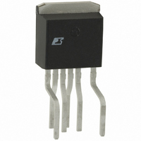
PKS606FN Power Integrations, PKS606FN Datasheet - Page 9

PKS606FN
Manufacturer Part Number
PKS606FN
Description
IC OFFLINE SWIT OTP OCP HV TO262
Manufacturer
Power Integrations
Series
PeakSwitch®r
Specifications of PKS606FN
Mfg Application Notes
PeakSwitch Design Guide AppNote
Output Isolation
Isolated
Frequency Range
250 ~ 304kHz
Voltage - Output
700V
Power (watts)
117W
Operating Temperature
-40°C ~ 150°C
Package / Case
TO-262-7 (Formed Leads), 5 Leads
Output Voltage
12 V
Input / Supply Voltage (max)
265 VAC
Input / Supply Voltage (min)
85 VAC
Duty Cycle (max)
65 %
Switching Frequency
47 KHz
Supply Current
25 uA
Operating Temperature Range
- 40 C to + 150 C
Mounting Style
Through Hole
For Use With
596-1198 - KIT REF DESIGN 36-72W MOTOR DRVR
Lead Free Status / RoHS Status
Lead free / RoHS Compliant
Other names
596-1125-5
Available stocks
Company
Part Number
Manufacturer
Quantity
Price
Company:
Part Number:
PKS606FN
Manufacturer:
power
Quantity:
15 000
Part Number:
PKS606FN
Manufacturer:
POWER
Quantity:
20 000
Primary Inductance Tolerance, L
This is the assumed primary inductance tolerance. A value of
12% is used by default. However, if specific information is
known from the transformer vendor, then this may be entered
in the grey override cell.
Number of Primary Turns, N
Total number of primary turns. For low leakage inductance it
is recommended that split primary construction be used.
Gapped core effective inductance, A
transformer vendor to specify the core gap.
Target B
The value entered here is used to calculate the number of
secondary turns. By default, a value of 2800 Guass is used,
slightly below the recommended maximum B
3000 Gauss. This accounts for the rounding down of the number
of calculated secondary turns in some designs.
Maximum Operating Flux Density, B
A maximum value of 3000 Gauss during normal operation is
recommended to limit the maximum flux density under start
up and output short circuit. Under these conditions, the output
voltage is low and little reset of the transformer occurs during
the MOSFET off time. This may allow the transformer flux
density to staircase above the normal operating level. A value
of 3000 Gauss at the peak current limit of the selected device,
together with the built-in protection features of PeakSwitch
provides sufficient margin to prevent core saturation under
startup or output short circuit conditions.
Figure 12. Transformer Primary Design Section of Design Spreadsheet.
Figure 13. Transformer Secondary Primary Parameters Section of Design Spreadsheet – Lumped into Single Output.
TRANSFORMER PRIMARY DESIGN PARAMETERS
LP
LP_TOLERANCE
NP
ALG
Target BM
BM
BAC
ur
LG
BWE
OD
INS
DIA
AWG
CM
CMA
TRANSFORMER SECONDARY DESIGN PARAMETERS
Lumped parameters
ISP
ISRMS
IRIPPLE
CMS
AWGS
M
(Gauss)
P
P_TOLERANCE
LG
M
(nH/T
(Gauss)
(%)
2
) used by the
M
value of
2800 Gauss
2624 Gauss
1588
0.28 mm
23.7 mm
0.33 mm
0.06 mm
0.28 mm
3.34 Amps
1.74 Amps
1.57 Amps
367 uHenries
789 Gauss
102 Cmils
208 Cmils/Amp Primary Winding Current Capacity (100 < CMA < 500)
349 Cmils
12 %
71
72 nH/T^2
30 AWG
24 AWG
The cycle skipping mode of operation used in PeakSwitch
can produce audio frequency displacements in the
transformer. To limit this noise, the transformer should
be designed such that the peak core flux density is below
3000 Gauss (300 mT). Following this guideline and using the
standard transformer production technique of dip varnishing
practically eliminates audible noise. A careful evaluation of the
audible noise performance should be made, using production
transformer samples before approving the design. When
ceramic capacitors that have Z5U dielectrics are used in clamp
circuits, they too may produce audible sound. They should be
replaced with capacitors that have a different dielectric, such
as polyester film.
Maximum Primary Wire Diameter, OD (mm)
By default, if the override cell is empty, double coated wire
is assumed and a standard wire diameter is chosen. The grey
override cells can be used to enter a wire diameter directly.
Primary wire size, DIA: (mm)
Primary wire gauge, AWG
Number of primary layers, L
Estimated core center leg gap length: L
Number of secondary turns, N
Secondary wire size, DIA
Secondary wire gauge, AWG
In multiple output designs N
output number) should also be used.
Peak Secondary Current
Secondary RMS Current
Output Capacitor RMS Ripple Current
Secondary Bare Conductor minimum circular mils
Secondary Wire Gauge (Rounded up to next larger standard
AWG value)
Typical Primary Inductance. +/- 12% to ensure a minimum
primary inductance of 328 uH
Primary inductance tolerance
Primary Winding Number of Turns
Gapped Core Effective Inductance
Target Peak Flux Density at Maximum Current Limit
Calculated Maximum Operating Flux Density, BM < 3000 is
recommended
AC Flux Density for Core Loss Curves (0.5 X Peak to Peak)
Relative Permeability of Ungapped Core
Gap Length (Lg > 0.1 mm)
Effective Bobbin Width
Maximum Primary Wire Diameter including insulation
Estimated Total Insulation Thickness (= 2 * film thickness)
Bare conductor diameter
Primary Wire Gauge (Rounded to next smaller standard AWG
value)
Bare conductor effective area in circular mils
S
: (mm)
Sx
S
S
, CM
Sx
AN-41
, AWG
g
: (mm)
Sx
(where x is the
Rev. E 02/07


