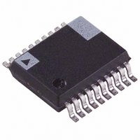
ADE7753ARSZ Analog Devices Inc, ADE7753ARSZ Datasheet - Page 35

ADE7753ARSZ
Manufacturer Part Number
ADE7753ARSZ
Description
IC ENERGY METERING 1PHASE 20SSOP
Manufacturer
Analog Devices Inc
Datasheet
1.ADE7753ARSZ.pdf
(60 pages)
Specifications of ADE7753ARSZ
Input Impedance
390 KOhm
Measurement Error
0.1%
Voltage - I/o High
2.4V
Voltage - I/o Low
0.8V
Current - Supply
3mA
Voltage - Supply
4.75 V ~ 5.25 V
Operating Temperature
-40°C ~ 85°C
Mounting Type
Surface Mount
Package / Case
20-SSOP (0.200", 5.30mm Width)
Meter Type
Single Phase
Ic Function
Single-Phase Multifunction Metering IC
Supply Voltage Range
4.75V To 5.25V
Operating Temperature Range
-40°C To +85°C
Digital Ic Case Style
SSOP
No. Of Pins
20
Lead Free Status / RoHS Status
Lead free / RoHS Compliant
For Use With
EVAL-ADE7753ZEB - BOARD EVALUATION AD7753
Lead Free Status / RoHS Status
Lead free / RoHS Compliant, Lead free / RoHS Compliant
Available stocks
Company
Part Number
Manufacturer
Quantity
Price
Part Number:
ADE7753ARSZ
Manufacturer:
ADI/亚德诺
Quantity:
20 000
Part Number:
ADE7753ARSZRL
Manufacturer:
ADI/亚德诺
Quantity:
20 000
Apparent Power Offset Calibration
Each rms measurement includes an offset compensation
register to calibrate and eliminate the dc component in the rms
value—see Channel 1 RMS Calculation and Channel 2 RMS
Calculation sections. The Channel 1 and Channel 2 rms values
are then multiplied together in the apparent power signal
processing. Since no additional offsets are created in the
multiplication of the rms values, there is no specific offset
compensation in the apparent power signal processing. The
offset compensation of the apparent power measurement is
done by calibrating each individual rms measurement.
APPARENT ENERGY CALCULATION
The apparent energy is given as the integral of the apparent
power.
The ADE7753 achieves the integration of the apparent power
signal by continuously accumulating the apparent power signal
in an internal 48-bit register. The apparent energy register
(VAENERGY[23:0]) represents the upper 24 bits of this internal
register. This discrete time accumulation or summation is
equivalent to integration in continuous time. Equation 31
expresses the relationship
where:
n is the discrete time sample number.
T is the sample period.
The discrete time sample period (T) for the accumulation
register in the ADE7753 is 1.1 µs (4/CLKIN).
Figure 75 shows this discrete time integration or accumulation.
The apparent power signal is continuously added to the internal
register. This addition is a signed addition even if the apparent
energy remains theoretically always positive.
Apparent
Apparent
Figure 74. Apparent Power Calculation Output Range
0x103880
0xAD055
0x5682B
0x00000
APPARENT POWER 100% FS
Energy
Energy
CHANNEL INPUTS: 0.5V/GAIN
VOLTAGE AND CURRENT
0x000
CALIBRATION RANGE
APPARENT POWER
=
=
{VAGAIN[11:0]}
T
Lim
APPARENT POWER 150% FS
∫
→
Apparent
0
0x7FF
⎧
⎪
⎨
⎪ ⎩
∑
n
∞
=
0
APPARENT POWER 50% FS
Apparent
0x800
Power
Power
(
t
)
02875-0-073
dt
(
nT
)
×
T
⎫
⎪
⎬
⎪ ⎭
Rev. A | Page 35 of 60
(30)
(31)
The 49 bits of the internal register are divided by VADIV. If the
value in the VADIV register is 0, then the internal active energy
register is divided by 1. VADIV is an 8-bit unsigned register. The
upper 24 bits are then written in the 24-bit apparent energy
register (VAENERGY[23:0]). RVAENERGY register (24 bits
long) is provided to read the apparent energy. This register is
reset to 0 after a read operation.
Figure 76 shows this apparent energy accumulation for full-scale
signals (sinusoidal) on the analog inputs. The three curves
displayed illustrate the minimum time it takes the energy register
to roll over when the VAGAIN registers content is equal to 0x7FF,
0x000, and 0x800. The VAGAIN register is used to carry out an
apparent power calibration in the ADE7753. As shown, the fastest
integration time occurs when the VAGAIN register is set to
maximum full scale, i.e., 0x7FF.
APPARENT POWER
0xFF,FFFF
0x80,0000
0x40,0000
0x20,0000
0x00,0000
VAENERGY[23:0]
Figure 76. Energy Register Rollover Time for Full-Scale Power
T
Figure 75. ADE7753 Apparent Energy Calculation
(Maximum and Minimum Power Gain)
ACTIVE POWER
6.26
SIGNAL = P
TIME (nT)
+
12.52
+
48
48
23
18.78
VADIV
VAENERGY [23:0]
25.04
APPARENT POWER ARE
ACCUMULATED (INTEGRATED) IN
THE APPARENT ENERGY REGISTER
%
0
VAGAIN = 0x7FF
VAGAIN = 0x000
VAGAIN = 0x800
ADE7753
TIME (minutes)
02875-0-075
02875-0-074
0
0


