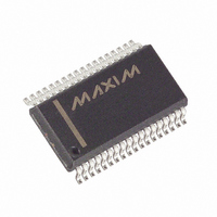
MAX5965BEAX+ Maxim Integrated Products, MAX5965BEAX+ Datasheet - Page 13

MAX5965BEAX+
Manufacturer Part Number
MAX5965BEAX+
Description
IC PSE CTRLR FOR POE 36SSOP
Manufacturer
Maxim Integrated Products
Type
Power Over Ethernet Controller (PoE)r
Datasheet
1.MAX5965AUAXT.pdf
(53 pages)
Specifications of MAX5965BEAX+
Applications
IP Phones, Power over LAN, Network Routers and Switches
Internal Switch(s)
No
Voltage - Supply
2.4 V ~ 3.6 V
Operating Temperature
-40°C ~ 85°C
Mounting Type
Surface Mount
Package / Case
36-BSOP (0.300", 7.5mm Width)
Product
PoE / LAN Solutions
Supply Voltage (max)
60 V
Supply Voltage (min)
32 V
Power Dissipation
1388.9 mW
Operating Temperature Range
- 40 C to + 85 C
Mounting Style
SMD/SMT
Input Voltage
60V
Supply Current
4.8mA
Digital Ic Case Style
SSOP
No. Of Pins
36
Uvlo
28.5V
Frequency
400kHz
Filter Terminals
SMD
Interface
I2C
Rohs Compliant
Yes
Controller Type
Power Supply
Lead Free Status / RoHS Status
Lead free / RoHS Compliant
17– 20
22, 25,
23, 26,
24, 27,
11–14
29, 32
30, 33
31, 34
7–10
PIN
High-Power, Quad, Monolithic, PSE Controllers
15
16
21
28
35
36
6
OUT4, OUT3,
SHD1–SHD4
OUT2, OUT1
DET1–DET4
SENSE4,
SENSE3,
SENSE2,
SENSE1
GATE4,
GATE3,
GATE2,
GATE1
SDAIN
NAME
A3–A0
DGND
AGND
AUTO
OSC
V
V
DD
EE
______________________________________________________________________________________
Serial Interface Input Data Line. Connect the data line optocoupler output to SDAIN (see the Typical
Operating Circuits). Connect SDAIN to SDAOUT if using a 2-wire, I
Address Bits. A3–A0 form the lower part of the device’s address. Address inputs default high with an
internal 50kΩ pullup resistor to V
its UVLO threshold or after a reset. The 3 MSBs of the address are set to 010.
Detection/Classification Voltage Outputs. Use DET1 to set the detection and classification probe voltages
on port 1. Use DET1 for the AC voltage sensing of port 1 when using the AC disconnect scheme (see the
Typical Operating Circuits).
Digital Ground. Connect to digital ground.
Positive Digital Supply. Connect to a digital power supply (reference to DGND).
Port Shutdown Inputs. Pull SHD_ low to turn off the external FET on port_. Internally pulled up to V
a 50kΩ resistor.
Analog Ground. Connect to the high-side analog supply.
MOSFET Source Current-Sense Negative Inputs. Connect to the source of the power MOSFET and
connect a current-sense resistor between SENSE_ and V
Port_ MOSFET Gate Drivers. Connect GATE_ to the gate of the external MOSFET (see the Typical
Operating Circuits).
MOSFET Drain-Output Voltage Senses. Connect OUT_ to the power MOSFET drain through a resistor
(100Ω to 100kΩ). The low leakage at OUT_ limits the drop across the resistor to less than 100mV (see the
Typical Operating Circuits).
Low-Side Analog Supply Input. Connect the low-side analog supply to V
capacitor between AGND and V
Auto or Shutdown Mode Input. Force AUTO high to enter auto mode after a reset or power-up. Drive low
to put the MAX5965A/MAX5965B into shutdown mode. In shutdown mode, software controls the
operational modes of the MAX5965A/MAX5965B. A 50kΩ internal pulldown resistor defaults to AUTO low.
AUTO latches when V
Software commands can take the MAX5965A/MAX5965B out of AUTO while AUTO is high.
Oscillator Input. AC-disconnect detection function uses OSC. Connect a 100Hz ±10%, 2V
offset sine wave to OSC. If the oscillator positive peak falls below the OSC_FAIL threshold of 2V, the ports
that have the AC function enabled shut down and are not allowed to power-up. When not using the AC-
disconnect detection function, leave OSC unconnected.
DD
or V
EE
EE
ramps up and exceeds its UVLO threshold or when the device resets.
DD
.
. The address values latch when V
for Power over Ethernet
FUNCTION
Pin Description (continued)
EE
(see the Typical Operating Circuits).
2
C-compatible system.
DD
EE
or V
(-48V). Bypass with a 1µF
EE
ramps up and exceeds
P-P
±5%, +1.3V
DD
with
13


