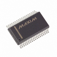
MAX5965BEAX+ Maxim Integrated Products, MAX5965BEAX+ Datasheet - Page 26

MAX5965BEAX+
Manufacturer Part Number
MAX5965BEAX+
Description
IC PSE CTRLR FOR POE 36SSOP
Manufacturer
Maxim Integrated Products
Type
Power Over Ethernet Controller (PoE)r
Datasheet
1.MAX5965AUAXT.pdf
(53 pages)
Specifications of MAX5965BEAX+
Applications
IP Phones, Power over LAN, Network Routers and Switches
Internal Switch(s)
No
Voltage - Supply
2.4 V ~ 3.6 V
Operating Temperature
-40°C ~ 85°C
Mounting Type
Surface Mount
Package / Case
36-BSOP (0.300", 7.5mm Width)
Product
PoE / LAN Solutions
Supply Voltage (max)
60 V
Supply Voltage (min)
32 V
Power Dissipation
1388.9 mW
Operating Temperature Range
- 40 C to + 85 C
Mounting Style
SMD/SMT
Input Voltage
60V
Supply Current
4.8mA
Digital Ic Case Style
SSOP
No. Of Pins
36
Uvlo
28.5V
Frequency
400kHz
Filter Terminals
SMD
Interface
I2C
Rohs Compliant
Yes
Controller Type
Power Supply
Lead Free Status / RoHS Status
Lead free / RoHS Compliant
High-Power, Quad, Monolithic, PSE Controllers
for Power over Ethernet
The MAX5965A/MAX5965B read using the MAX5965A/
MAX5965B’s internally stored command byte as an
address pointer, the same way the stored command
byte is used as an address pointer for a write. The point-
er autoincrements after reading each data byte using the
same rules as for a write. Thus, a read is initiated by first
configuring the MAX5965A/MAX5965B’s command byte
by performing a write. The master now reads ‘n’ consec-
utive bytes from the MAX5965A/MAX5965B, with the first
data byte read from the register addressed by the initial-
ized command byte. When performing read-after-write
verification, remember to reset the command byte’s
address because the stored control byte address autoin-
crements after the write.
When the MAX5965A/MAX5965B operate on a 2-wire
interface with multiple masters, a master reading the
MAX5965A/MAX5965B should use repeated starts
between the write which sets the MAX5965A/
MAX5965B’s address pointer, and the read(s) that take
the data from the location(s). It is possible for master 2 to
take over the bus after master 1 has set up the
Figure 11. Control and Single Data Byte Received
Figure 12. ‘n’ Data Bytes Received
26
S
S
ACKNOWLEDGE FROM THE
ACKNOWLEDGE FROM THE
______________________________________________________________________________________
HOW CONTROL BYTE AND DATA BYTE MAP
HOW CONTROL BYTE AND DATA BYTE MAP
SLAVE ADDRESS
SLAVE ADDRESS
MAX5965A/MAX5965B
MAX5965A/MAX5965B
Operation with Multiple Masters
INTO THE REGISTER
INTO THE REGISTER
Message Format for Reading
R/W
R/W
0
0
A
A
ACKNOWLEDGE FROM THE
ACKNOWLEDGE FROM THE
D15 D14 D13 D12 D11 D10
D15 D14 D13 D12 D11 D10
CONTROL BYTE
CONTROL BYTE
MAX5965A/MAX5965B
MAX5965A/MAX5965B
MAX5965A/MAX5965B’s address pointer but before mas-
ter 1 has read the data. If master 2 subsequently resets
the MAX5965A/MAX5965B’s address pointer then master
1’s read may be from an unexpected location.
Address autoincrementing allows the MAX5965A/
MAX5965B to be configured with fewer transmissions
by minimizing the number of times the command
address needs to be sent. The command address
stored in the MAX5965A/MAX5965B generally incre-
ments after each data byte is written or read (Table 5).
The MAX5965A/MAX5965B are designed to prevent
overwrites on unavailable register addresses and unin-
tentional wrap-around of addresses.
Table 5. Autoincrement Rules
ADDRESS RANGE
COMMAND BYTE
D9
0x00 to 0x26
D9
D8
0x26
D8
A
A
ACKNOWLEDGE FROM THE
Command Address Autoincrementing
ACKNOWLEDGE FROM THE
D7
D7
D6
D6
Command address autoincrements
after byte read or written
Command address remains at 0x26
after byte written or read
D5
AUTOINCREMENT BEHAVIOR
D5
DATA BYTE
D4
DATA BYTE
D4
1 BYTE
n BYTES
D3
MAX5965A/MAX5965B
D3
MAX5965A/MAX5965B
D2
D2
MEMORY WORD ADDRESS
MEMORY WORD ADDRESS
D1
D1
AUTOINCREMENT
AUTOINCREMENT
D0
D0
A
A
P
P


