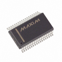
MAX5965BEAX+ Maxim Integrated Products, MAX5965BEAX+ Datasheet - Page 34

MAX5965BEAX+
Manufacturer Part Number
MAX5965BEAX+
Description
IC PSE CTRLR FOR POE 36SSOP
Manufacturer
Maxim Integrated Products
Type
Power Over Ethernet Controller (PoE)r
Datasheet
1.MAX5965AUAXT.pdf
(53 pages)
Specifications of MAX5965BEAX+
Applications
IP Phones, Power over LAN, Network Routers and Switches
Internal Switch(s)
No
Voltage - Supply
2.4 V ~ 3.6 V
Operating Temperature
-40°C ~ 85°C
Mounting Type
Surface Mount
Package / Case
36-BSOP (0.300", 7.5mm Width)
Product
PoE / LAN Solutions
Supply Voltage (max)
60 V
Supply Voltage (min)
32 V
Power Dissipation
1388.9 mW
Operating Temperature Range
- 40 C to + 85 C
Mounting Style
SMD/SMT
Input Voltage
60V
Supply Current
4.8mA
Digital Ic Case Style
SSOP
No. Of Pins
36
Uvlo
28.5V
Frequency
400kHz
Filter Terminals
SMD
Interface
I2C
Rohs Compliant
Yes
Controller Type
Power Supply
Lead Free Status / RoHS Status
Lead free / RoHS Compliant
High-Power, Quad, Monolithic, PSE Controllers
for Power over Ethernet
Setting DET_EN_/CLASS_EN_ to 1 (Table 18) enables
load detection/classification, respectively. Detection
always has priority over classification. To perform clas-
sification without detection, set the DET_EN_ bit low
and CLASS_EN_ bit high.
In manual mode, R14h works like a pushbutton. Set the
bits high to begin the corresponding routine. The bit
clears after the routine finishes.
EN_HP_CL_, EN_HP_ALL together with CL_DISC
(R17h[2]) and ENx_CL6 (R1Ch[7:4]) are used to program
the high-power mode. See Table 3 for details.
Setting BCKOFF_ to 1 (Table 19) enables cadence tim-
ing on each port where the port backs off and waits
2.2s after each failed load discovery detection. The
Table 18. Detection and Classification Enable Register
Table 19. Backoff and High-Power Enable Register
34
EN_HP_ALL
EN_HP_CL6
EN_HP_CL5
EN_HP_CL4
BCKOFF4
BCKOFF3
BCKOFF2
BCKOFF1
CLASS_EN4
CLASS_EN3
CLASS_EN2
CLASS_EN1
DET_EN4
DET_EN3
DET_EN2
DET_EN1
______________________________________________________________________________________
SYMBOL
SYMBOL
ADDRESS = 15h
ADDRESS = 14h
BIT
BIT
7
6
5
4
3
2
1
0
7
6
5
4
3
2
1
0
R/W
R/W
R/W
R/W
R/W
R/W
R/W
R/W
R/W
R/W
R/W
R/W
R/W
R/W
R/W
R/W
R/W
R/W
High-power detection enabled
Class 6 PD high-power enabled
Class 5 PD high-power enabled
Class 4 PD high-power enabled
Enable cadence timing on port 4
Enable cadence timing on port 3
Enable cadence timing on port 2
Enable cadence timing on port 1
Enable classification on port 4
Enable classification on port 3
Enable classification on port 2
Enable classification on port 1
Enable detection on port 4
Enable detection on port 3
Enable detection on port 2
Enable detection on port 1
When entering auto mode, R14h defaults to FFh. When
entering semi or manual modes, R14h defaults to 00h.
A reset or power-up sets R14h = AAAAAAAAb where A
represents the latched-in state of the AUTO input prior
to the reset.
IEEE 802.3af standard requires a PSE that delivers
power through the spare pairs (midspan PSE) to have
cadence timing.
A reset or power-up sets R15h = 0000XXXXb where ‘X’
is the logic AND of the MIDSPAN and AUTO inputs.
DESCRIPTION
DESCRIPTION


