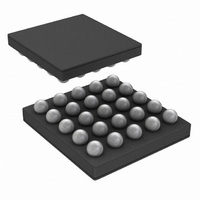
LP5520TL/NOPB National Semiconductor, LP5520TL/NOPB Datasheet - Page 16

LP5520TL/NOPB
Manufacturer Part Number
LP5520TL/NOPB
Description
IC LED DRIVER RGB 25-USMD
Manufacturer
National Semiconductor
Series
PowerWise®r
Type
RGB LED Driverr
Datasheet
1.LP5520TLNOPB.pdf
(34 pages)
Specifications of LP5520TL/NOPB
Constant Current
Yes
Topology
PWM, Step-Up (Boost)
Number Of Outputs
3
Internal Driver
Yes
Type - Primary
Backlight, Light Management Unit (LMU)
Type - Secondary
RGB, White LED
Frequency
1.22kHz, 19.52kHz
Voltage - Supply
2.9 V ~ 5.5 V
Voltage - Output
5 V ~ 20 V
Mounting Type
Surface Mount
Package / Case
25-MicroSMD
Operating Temperature
-30°C ~ 85°C
Current - Output / Channel
60mA
Internal Switch(s)
Yes
Efficiency
87%
Lead Free Status / RoHS Status
Lead free / RoHS Compliant
Other names
LP5520TLTR
www.national.com
PWM mode defined by <seq_mode1> and <seq_mode2> control bits of rgb_control (00H) register:
CURRENT CONTROL OF THE LEDS
LP5520 has separate 8-bit current control for each LED out-
put. In manual mode the current for red LED is controlled with
current_control_r (01H) register, for green LED with
current_control_g
current_control_b (03H). Output current can be calculated
with formula: current (mA) = code x 0.235, for example 20
mA current is obtained with code 85 (55H).
In automatic and stand-alone modes the LED current values
programmed in EEPROM are used, and the current control
registers have no effect. There are two ways to change the
default current if needed. The defaults can be changed per-
manently by programming new values to the EEPROM. The
other option is to make a temporary change by writing new
current values in SRAM. Since this is not normally needed, it
is only described in the Calibration Application Note AN1459.
OUTPUT ENABLES
R
able bits of the rgb_control (00H) register:
OUT
<en_b>
(bit 2)
<en_g>
(bit 1)
<en_r>
(bit 0)
, G
OUT
and B
<seq_mode1>
0 Blue LED output B
1 Blue LED output B
0 Green LED output G
1 Green LED output G
0 Red LED output R
1 Red LED output R
(bit 7)
OUT
0
0
1
1
(02H)
output activity is controlled with 3 en-
and
OUT
OUT
OUT
OUT
for
<seq_mode0>
OUT
OUT
disabled
enabled
disabled
enabled
blue
(bit 6)
disabled
enabled
0
1
0
1
LED
with
Normal mode
Sequential mode with 2 PWM pulses per trigger
Sequential mode with 3 PWM pulses per trigger
Sequential mode with 4 PWM pulses per trigger
16
PWM control inputs PWMR, PWMG and PWMB can be used
as external output enables in normal and automatic mode. In
the sequential mode these inputs are the trigger inputs for
respective outputs.
FADE IN / FADE OUT
LP5520 has an automatic fade in and out for the LED outputs.
Fading makes the transitions smooth in on/off switching or
when brightness is changed. It is not applied for the changes
caused by the compensation algorithm. The fade can be
turned on and off using the <en_fade> bit in the rgb_con-
trol (00H) register. The fade time is constant 520 ms and it
does not depend on how big the brightness change is. The
white balance is maintained during fading. Fading is off in the
Stand-alone mode.
Fading only works in automatic mode. The LED current reg-
isters should be written to 0 for proper Fade operation. When
the LEDs are turned on with Fading, it is best to set the bright-
ness first and then enable the outputs and automatic mode.
The LEDs can be turned off then by turning off the automatic
mode (write rgb_auto to 0).
<en_fade>(bit 5)
Mode
0
1
Automatic fade disabled
Automatic fade enabled


