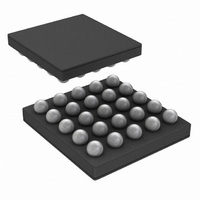
LP5520TL/NOPB National Semiconductor, LP5520TL/NOPB Datasheet - Page 6

LP5520TL/NOPB
Manufacturer Part Number
LP5520TL/NOPB
Description
IC LED DRIVER RGB 25-USMD
Manufacturer
National Semiconductor
Series
PowerWise®r
Type
RGB LED Driverr
Datasheet
1.LP5520TLNOPB.pdf
(34 pages)
Specifications of LP5520TL/NOPB
Constant Current
Yes
Topology
PWM, Step-Up (Boost)
Number Of Outputs
3
Internal Driver
Yes
Type - Primary
Backlight, Light Management Unit (LMU)
Type - Secondary
RGB, White LED
Frequency
1.22kHz, 19.52kHz
Voltage - Supply
2.9 V ~ 5.5 V
Voltage - Output
5 V ~ 20 V
Mounting Type
Surface Mount
Package / Case
25-MicroSMD
Operating Temperature
-30°C ~ 85°C
Current - Output / Channel
60mA
Internal Switch(s)
Yes
Efficiency
87%
Lead Free Status / RoHS Status
Lead free / RoHS Compliant
Other names
LP5520TLTR
www.national.com
using the sensor calibration data from EEPROM. This EEP-
ROM address is then used to get the PWM values for each
output. The second input S2_IN can be used for example for
ambient light measurement. The ADC data from selected in-
put can be read through the serial interface. Control bit
<comp_sel> can be used to select which input is used for
compensation.
Current setting for each LED comes from EEPROM in the
automatic mode. The same current values should be pro-
grammed as were used in the calibration. Current control
range is from 0 to 60 mA with 8-bit resolution and the step
size is 235 µA.
Common Brightness Control for all LEDs can be done using
the pwm_brightness (05H) register. The pwm_brightness
register makes 8 level logarithmic brightness control with 3
bits. An automatic fade function makes possible smooth turn-
on, turn-off and brightness changes of the LEDs. White bal-
ance is maintained during fading.
A brightness correction value can be given for each LED. The
PWM value obtained from the EEPROM memory will be mul-
tiplied by this correction value. This feature can be used for
example for LED aging compensation or for color adjustment
by user. These values are kept in R_correction (0AH),
G_correction (0BH) and B_correction (0CH) registers. The
correction multiplier can be between 0 and 2.
Due to LED self-heating, the temperature sensor and the LED
temperatures will differ. The difference depends on the ther-
mal structure of the display module and the distance between
the sensor and the LEDs. This temperature difference can be
compensated by storing the temperature difference value at
highest power (100% red LED PWM) in the EEPROM mem-
ory. The system then corrects the measured temperature
based on the actual PWM value used. The correction as-
sumes that the red LED PWM value is representing the whole
RGB LED power consumption.
Sequential (non-overlapping) drive is possible using external
PWM control inputs to trigger a new sequence in each LED
BRC input PWM duty cycle conversion to brightness control
BRC duty cycle threshold values (%)
increasing
20
35
48
58
68
82
97
1
decreasing
15
28
42
52
62
75
90
0
(% of maximum)
Intensity
12.5
100
0.8
1.6
3.1
6.3
off
25
50
6
output. 60 mA maximum current setting makes possible 20
mA maximum averaged current for each output in the non-
overlapping mode.
STAND-ALONE MODE
In stand-alone mode the operation is controlled through a
single PWM brightness input, BRC. After power-up or reset
the LP5520 is ready for stand-alone operation without any
setup through the serial interface. The stand-alone mode is
entered with a rising edge in the BRC input. The boost con-
verter will operate in adaptive mode. The LED current settings
are read from EEPROM. The LED brightness is controlled
with a PWM signal in the BRC input. The BRC PWM frequen-
cy should be between 2 and 10 kHz. The PWM signal in the
BRC input is not used as such for the LED outputs, but it is
converted to 3-bit value and a logarithmic brightness control
is based on this 3-bit value, as shown in the following table.
There is hysteresis in the conversion to avoid blinking when
the BRC duty cycle is close to a threshold. When the PWM
pulses end in the BRC input and the input stays low, the circuit
will go to the stand-by mode.
The following picture shows the waveforms in BRC input and
ROUT output in the stand-alone mode. The circuit is in stand-
by mode until the first rising edge in BRC input is detected.
The circuit starts up and the outputs activate after 30 ms from
the first rising edge in BRC. The BRC frequency is assumed
to 2 kHz in this example giving 0.5 ms BRC period. When the
duty cycle changes in BRC, it takes two BRC periods before
the change is reflected in the output. When BRC goes per-
manently low, the circuit will enter stand-by mode after 15 ms
from the last BRC pulse.
All controls through the serial interface can be used in the
stand-alone mode. The stand-alone mode must be inhibited
in automatic and manual modes by writing the control bit
<brc_off> high and by keeping BRC input low.
Recommended BRC PWM control values
increasing
10
28
40
53
63
75
88
99
decreasing
10
22
32
47
58
70
85
0


